|
Advertisement / Annons: |
3D Printing:
|
Contents:
Note: |
11, Mechanical calibration:Restarting the 3D-printer project:My 3D-printer project got stuck for a long time. Now I'm restarting it again. I have discussed these problems with a friend and now after many hours of thinking I understand I have done something wrong with the earlier mechanical adjustment. Adjusting the printer board: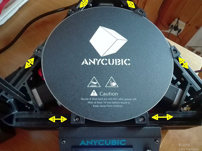
I find that the bottom printer bed was misaligned with 2mm. Not good because then I can't use the full size of the printer volume. This was very easy to correct. Adjusting the bottom mechanical stop: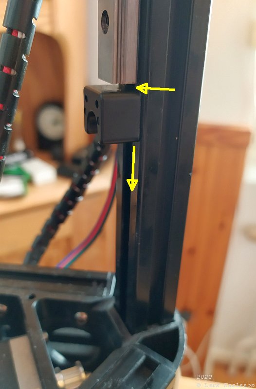
When I tested that the printer head could go all the way to the rim of the printer volume I found that the bottom stop was set to high. I lowered it 5 mm. I also adjusting the slider bearing to have a gap of 2 mm to the stop. Not more because then the roller balls can fall out from the slider. This will give me more headroom to the 300 mm height limit. Repair of tilted stop screw and adjust top stop: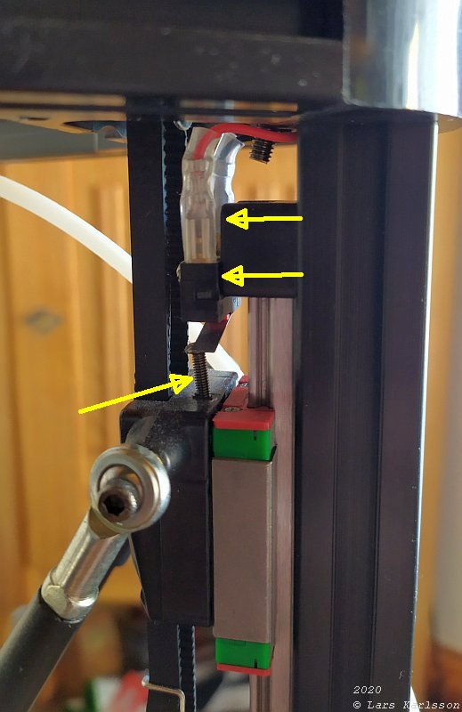
I repair the tilted screw, I only had to unscrew it and screw it in again at correct angle. As you see in the picture I don't use all the length of the slider rail, I get about 15 mm too low height. This is something that I want to correct. I move the switch to the upper edge of the mechanical stop and then screw in the stop screw 5 mm. See the following images how I did that. Rotation of the upper stop 180 degrees: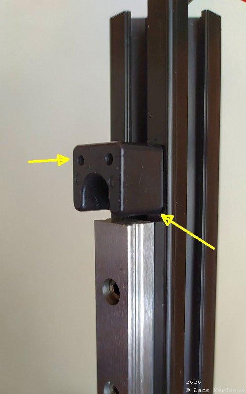
After I had rotated the mechanical stop 180 degrees I now have the screw holes that hold the upper limit switch at the upper edge, a move upwards of 10 mm. I also set a gap of 2 mm between the slider and the stop. Together with that the screw is 5 mm deeper and the extra gap of 2 mm at bottom I now have 19 mm extra. After adjusting the upper limit switch: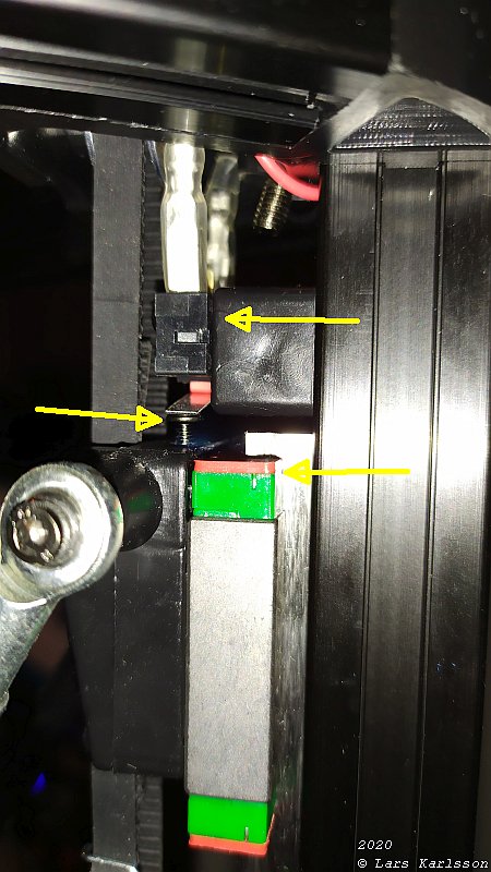
This is how it looks after I have done these rebuilding / adjustments. I use the red plastic part of the slider when I calibrate the mechanical stop for all three sliders. Maybe I get a precision of +/- 1 mm. I now have a printer circle of 235 mm, compare to standard 230 mm. The printer height is 315 mm compare to standard 300 mm but to have some margin I set it to 310 mm. To use this extra size the setup of the printer must be changed.
|
|