|
Advertisement / Annons: |
My astronomy project:
|
Content:
Note: |
7, Start assembling circuit board:Now it's time to start assembling the circuit board. As I do it with a prototype board it's a bit time consuming. The reason that I could use a prototype board is that I only use the most elementary functions. I don't use it as a stand alone controller, it's controlled by the Raspberry computer. Very few circuits needed. Push buttons and LEDs: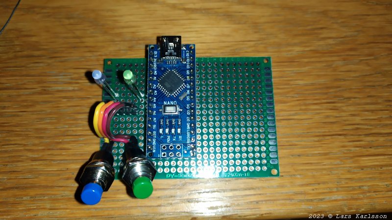
According to the schematics above I have started setup the hardware. I use a general prototype board to make it easy to add some special futures if needed. I started with the Arduino and the two LEDs and two push buttons. Blue button is focuser moving outwards and green is moving inwards. After adding the resistor network I could test the push buttons.
The voltage of pin A0 (analogue in): I feed the resistor network with 5 Volt, not 8 Volt as it should be, maybe cause a problem. Later test showed that it wasn't a problem. Stepper motor driver circuits: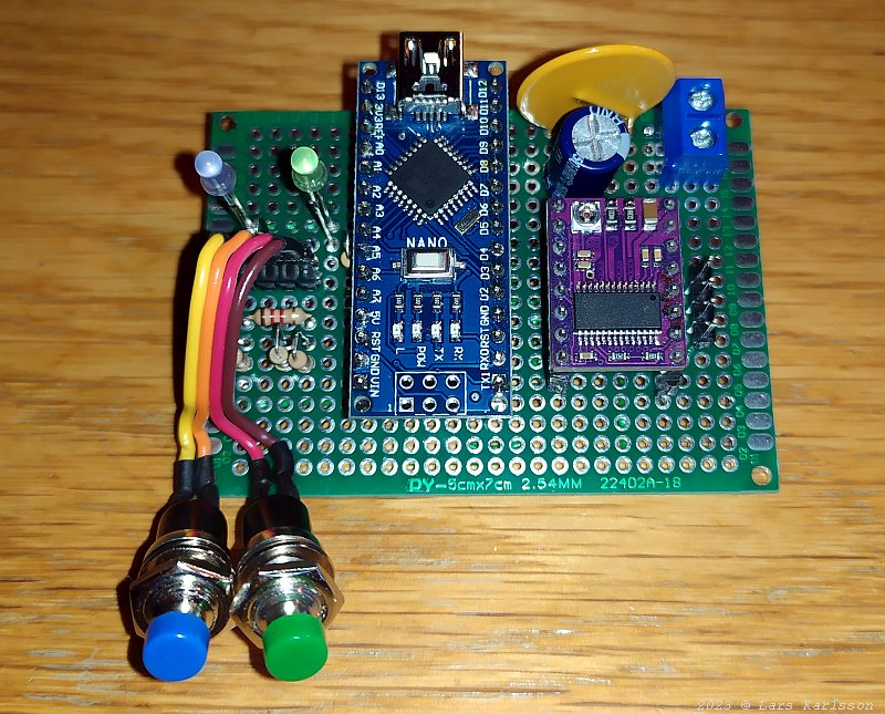
To the right, the purple circuit board, the stepper motor driver. It's a DRV8825 driver, data sheet pdf: DRV8825. The big yellow device is an electronic fuse, a PTC fuse. Two capacitors filter the power line, one big electrolytic and one small ceramic. 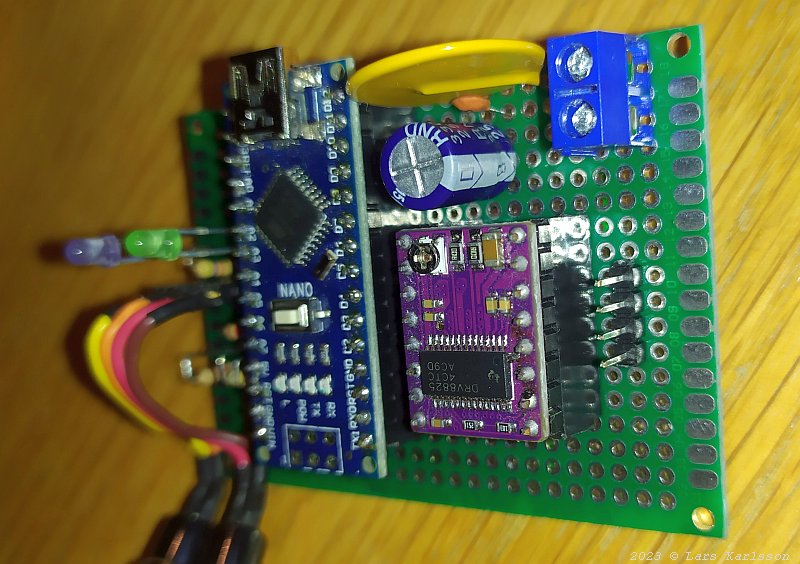
The small ceramic capacitor is not in the original drawing, something I added, the small one below the big yellow polyfuse. Pulse width modulated driver always introduce high frequency disturbance which a small ceramic capacitor reduce more efficient. The potentiometer on the driver board set the limit of the motor current. The blue socket up at right is the inlet for 12 Volt which power the stepper motor. My earlier motor focuser could only handle 8 Volt and I needed a DC/DC converter from 12 to 8 Volt. With this new focus controller it's not necessary. 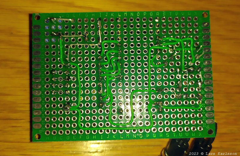
The backside of the circuit board, always a bit messy when using prototype boards. I highly recommend you to buy the original circuit board which I will do if I build one more of this stepper motor controller. I haven't cut the pins of the LEDs yet, I have to adjust the length of them to match the later box I will 3D-print. Power up the driver:After carefully checking that all connections is correct I connect the 12 Volt power, the red an black cable at bottom right. Still the stepper motor wasn't connected. Connect a Voltmeter to the output connecter on the circuit board. Test one output at each time, A1-A2 and B1-B2. Push the IN/OUT buttons to check that I get 12 Volt out from the connector, and it worked. Power it down, do a check how the cable to the stepper motor is connected to the coils. Coil A is connected to black and red cable, coil B is connected to green and blue cable. 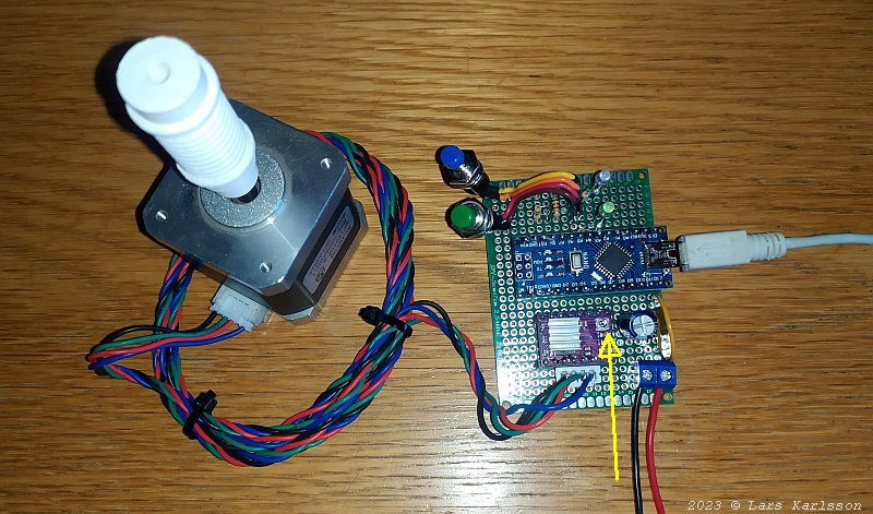
Found that I must mix the two cables green and red to get it correct connected to the driver board according to MyFocusePro2 standard. Connect the power once again, push the IN button and the stepper motor starts rotating. Now the motor current must be set correct. I have an ampere meter connected to the 12 Volts power supply. I read a very high 1 Ampere, it must be lowered quickly, otherwise the driver will burn up. Follow the instructions in the MyFocuserPro2 document and could lower it to 0.03 Ampere when motor rotate. Later after practical testing I had to increase the current to 300 mAmp with this big stepper motor. The current is adjusted with the little potentiometer at the driver board where the yellow arrow point, you should use a plastic screwdriver when trim this current. 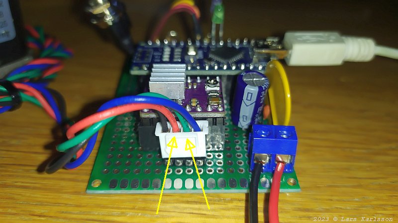
It was these two cable that I had to change with each other. Later when it's connected to the focuser it could be that it rotate in wrong direction, then I have to mix the green and blue (or red and black) cable. You found information in the MyFocuserPro2 document. Later when I tested the focuser I found that I had to reverse the direction and shifted the green and blue wire. Here is a video with more general information about Arduino and stepper motors:
|
|