|
Advertisement / Annons: |
3D CAD drawing:
|
Contents:
Note: |
3, Timing belt length calculation:Info:Before I can make an exact drawing of the bracket I must know the center to center distance between the two pulleys. I can't order a timing belt in the exact length that I want, I have to adapt my construction after what timing belts that are available. I found that there is a 400 mm length timing belt that I can use, now I calculate backwards to find the distance, center to center. Bracket version 3: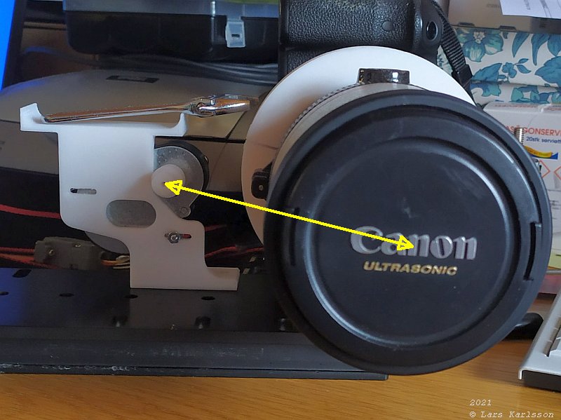
This is how it looks, with the version 2 bracket, the big pulley is centered around the lens optical axis. And it's also tilted relative the dovetail. When the motor is at the middle position in the elongated holes the C-C distance is about 90 mm. The nearest size of timing belt I found was 400 mm. You can use the timing belt calculator from Bearing Boys to find the length of the timing belt:
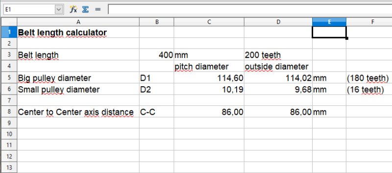
I wanted to have the Center to Center distance between the two pulleys, I tested with different C - C distances until I got the length 400 mm which was the nearest length of timing belt I found. I got the C - C to 86 mm. There is a little bit different if you use the pitch diameter or the outside diameter. Table with data of pulleys:
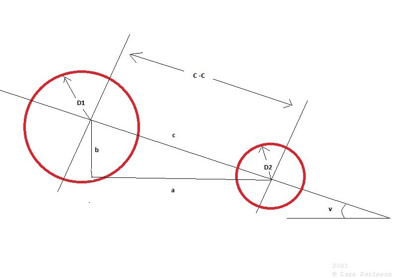
The C - C distance is the c-side of the triangle above. But what we want is the a-side. That is because the motor axis and the lens axis is not on the same height. But we can easy find this a-length, we use the old Greek Phythagorean theorem. It says that c2 = a2 + b2. 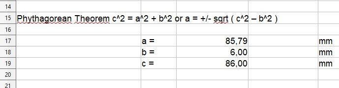
I measure the height of the motor axle above the dovetail and get 53 mm, the lens optical axis is 59 mm. The difference is 6 mm, that is the b side in the image above (the image is mirrored), if we use the 86 mm I calculated above as the c-side we get a-side to 85.8 mm, no much difference. My plan is to have the motor adjustable +/- 5 mm in distance to the lens. That compare to a difference of +/- 10 mm length difference of the timing belt. Later when the new 3D printed parts was installed I measure the center to center distance to 85 mm.
Update: 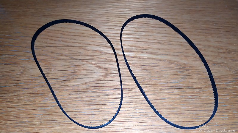
Two new timing belts dropped down in the mail box. Perfect, now I can find out the exact dimension of my motor bracket. 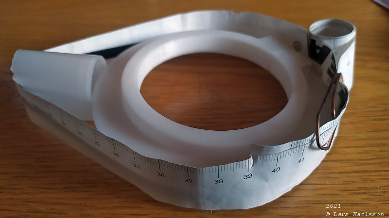
This is a 400 mm timing belt, but how do they measure the length of it ? I found the outside length to be 404 mm. 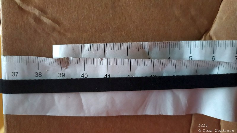
And the inside length of it is 399 mm, almost exact. My measure method was very primitive. This mean I should use the pulleys diameter at the valley of the teeth. The new 180 teeth pulley is printing out now, need 7 more hours until it's finished. |
|
|