|
Advertisement / Annons: |
3D CAD drawing:
|
Contents:
Note: |
1, CAD for motor focusing bracket:Introduction:My first sharp CAD. I have now practicing enough to do my first 3D CAD drawing, a bracket for the motor focuser. It should not be too difficult. Old steel bracket: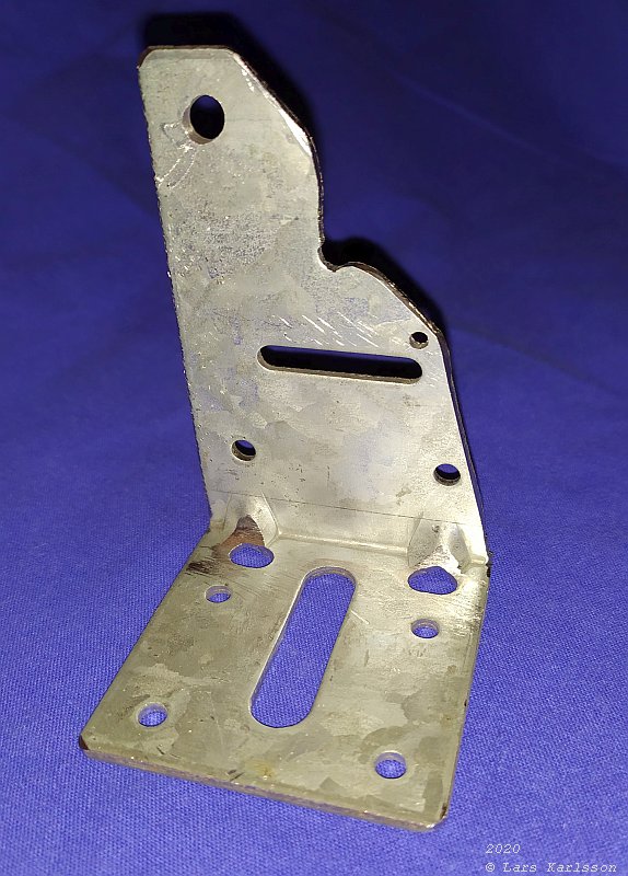
This is the old bracket I made to my 300 mm lens setup. It's okay but I'm eager to try my new skills in 3D CAD drawing and later 3D printing. How can I replace this steel bracket with one 3D printed bracket made of plastic ? Remember I'm new to this, maybe there are much better methods to do this. Search for FreeCAD on YouTube and you find a lot of tutorials how to use FreeCAD. The base 2D CAD in FreeCAD: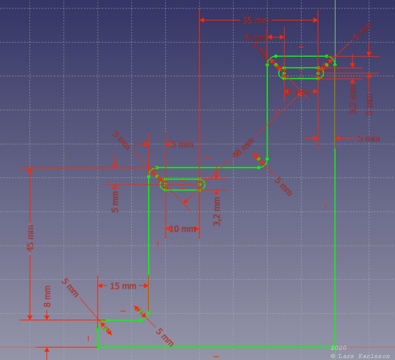
This CAD is based on a numbers of parameters. With that I can easily go back and change the dimension and the 3D model change too. Very handy ! I do the 2D CAD in the Sketcher mode and the 3D CAD in the Pad Design mode. FreeCAD, Pad: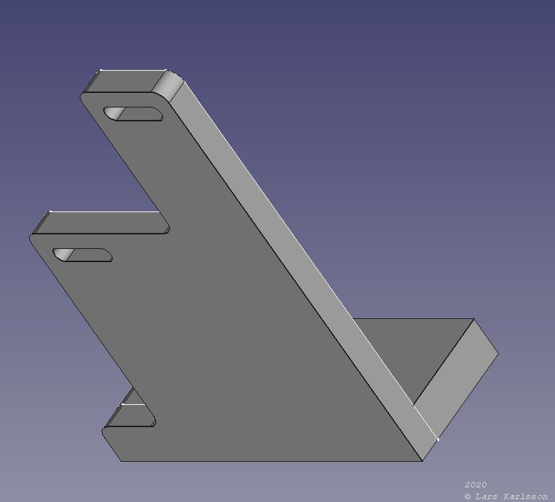
In FreeCAD they called a stretch for Pad. You just grab an area in the 2D drawing (in Pad Design) and stretch it out to the third dimension. The elongated holes are for the motor and used to stretch the timing belt. It can adjust the position 10 mm back and forth, it's made for 3 mm screws. The foot of the bracket: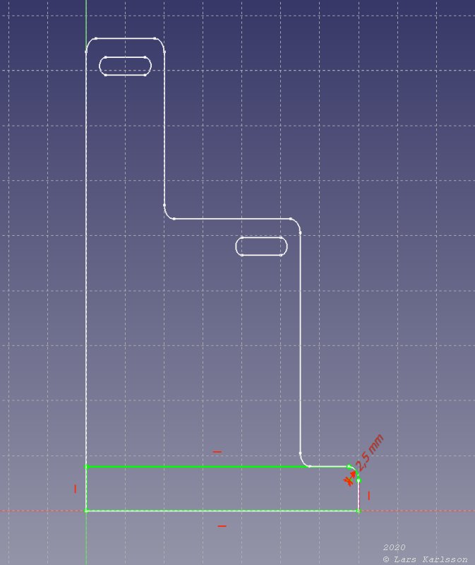
As you maybe noted that I had added a foot to the bracket in the image above. I did it in the Sketcher mode. A limited area that I can stretch in Pad Design mode. One strange thing, I have to set the radius to 2.5 mm, not 5 mm as I used earlier in the drawing. 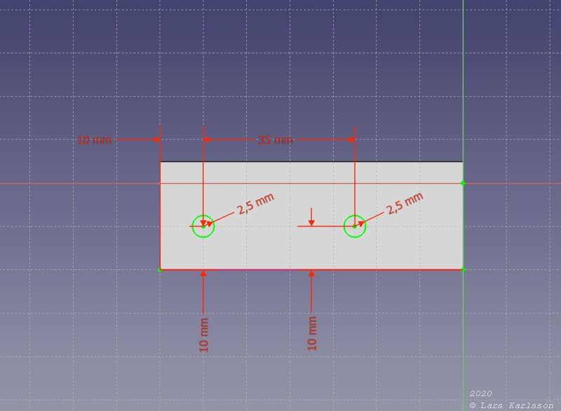
The foot is attached to the Vixen tail on the mount. I need two holes for the screws that hold it in place and I added the holes in the 2D drawing. Minus add the foot's holes: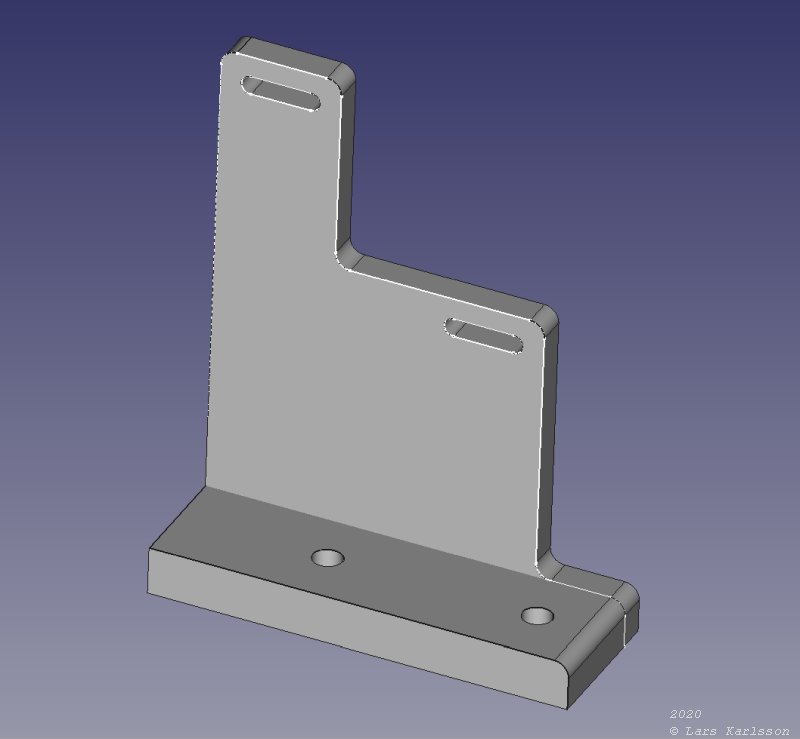
In Pad Design mode I used a "minus" add (it removes material). That function made the holes to go through the stretched foot. As an option I let the holes be threaded with M6, I'm not sure if they are there, let's see what happens when I print it out later. The main standing bracket is 5 mm thick and the foot 8 mm thick. Will it be enough to make it stable ? Next step is to add some structure to the surfaces, looks nicer and save some plastic material and let it 3D print faster. One big problem, I haven't got the 3D-printer in work yet. I think it's a mechanical calibration problem. The positive thing, I found a video that go trough the calibration process for a delta 3D printer. |
|
|