|
Advertisement / Annons: |
My astronomy project:
|
Content:
Note: |
Page III.2: Building the mechanism for the roofThis time I start with the complicated roof mechanism. I will try to build something else than the traditionally sliding roof. I want a building with low walls to let me point the telescope at low altitudes. With a sliding roof it must be doors that open for the telescope or have walls that can be folded down. Here you can follow my alternative solution, it's a combination of idea 1 and 3 above. 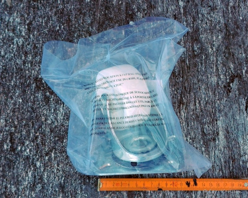
The roof will rest on arms, caster wheels will be used as hinges. 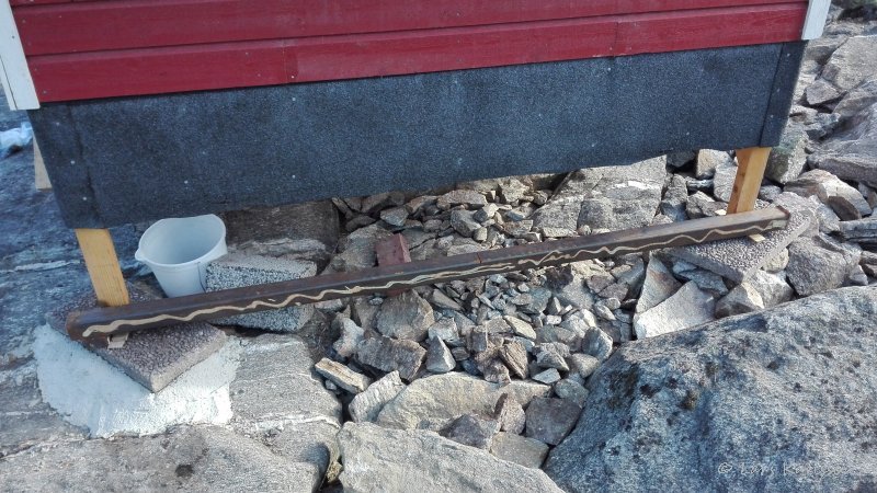
And I also need a heavy steel bar, my girlfriend found one for me. It has the dimension 60 x 60 x 2300 mm and a thickness of 6 mm. It's heavy and will act as a counter balance weight among other things. Do your girl/boyfriend deliver such a thing for you? 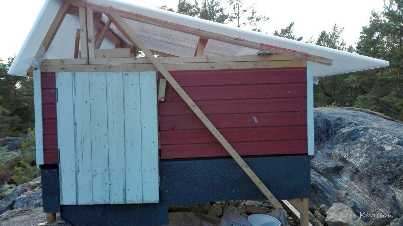
Here you can see one of the arms, it's just nailed in position now when I test if it give the correct geometry. I have the door that occupy part of the wall and can't let the arm pass over the door. You must be very careful about the geometry, I want the roof move to right and then lower down so it will not hide the view. The hinge must have some strong base to connect to, the cross in the ring mark the center of the rotation axis. 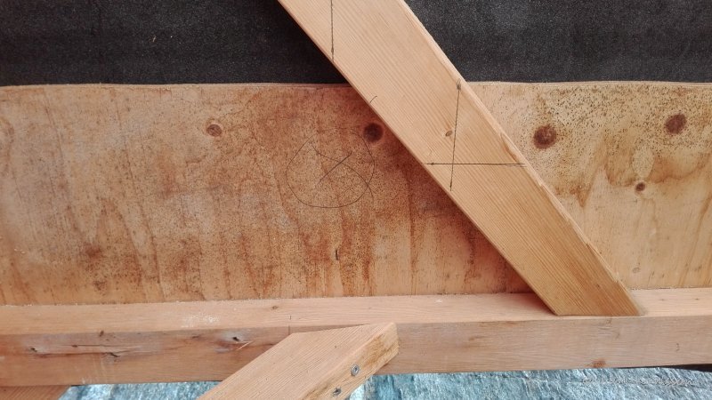
A wooden part was cut to fit here. 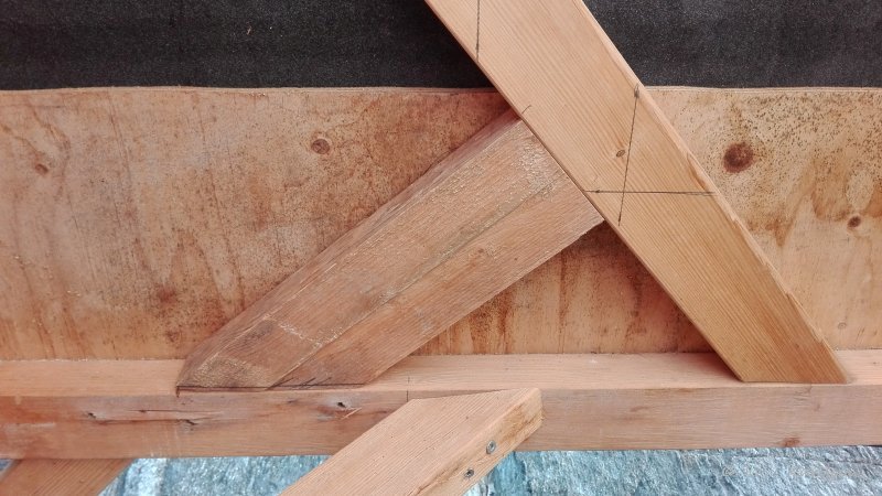
Looks good, this will be stable and that is important. 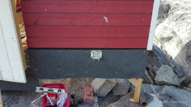
Here is the hinge mounted on outside of the wall, and the wheel is of course of no use of so I have removed it. 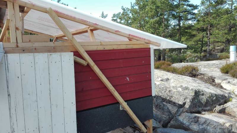
Here is the arm mounted at the lower hinge but the upper end isn't mounted yet. 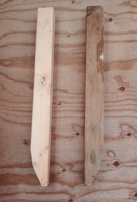
Inside the roof I need some guiders, when closing the roof it must come in correct position, made of wood. 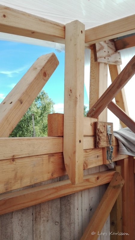
Here the roof is in closed position and the guide has moved it sideways to correct position. Later I will mount a stainless steel plate at top of the wood that it move against, it will lower the friction and the wear. This guiders also strength the roof. 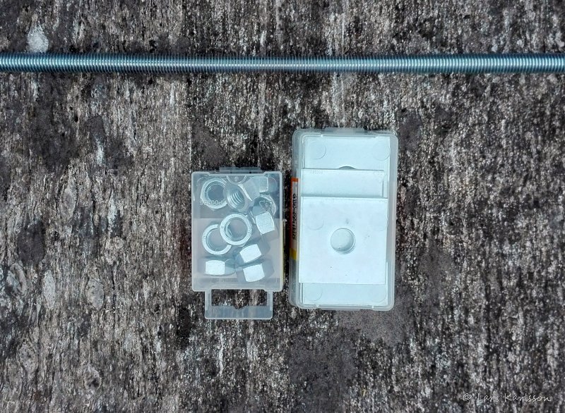
More parts needed, four 0.25 meters threaded rods, nuts and washer. 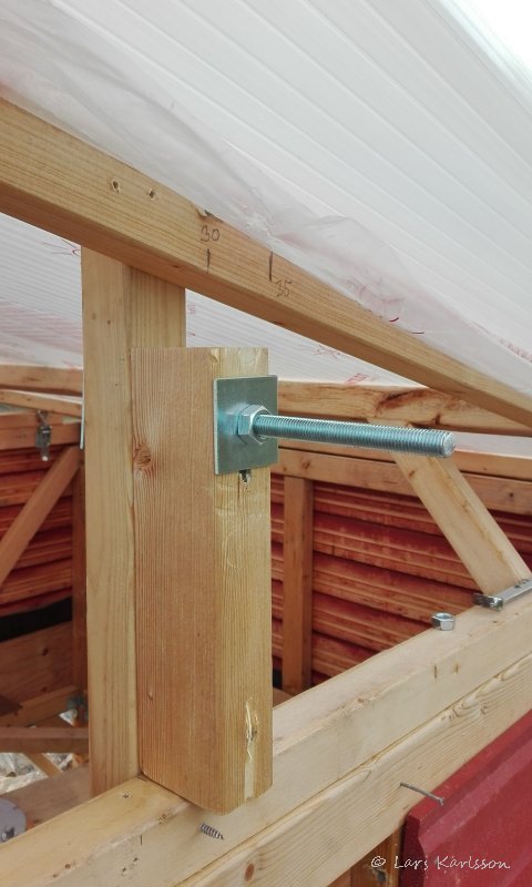
This will be the upper hinge to the arm. Later I must have a metal tube around the screw. Now I'm just testing. 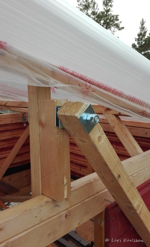
The size of the threaded rod is M12. 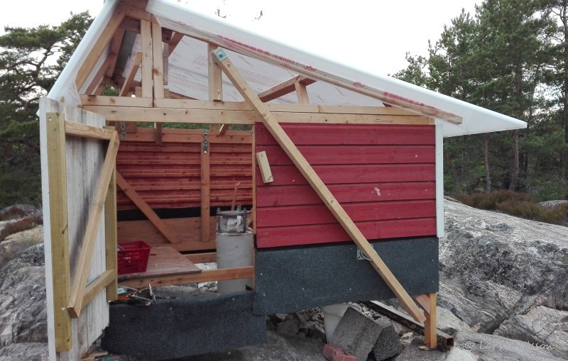
Overview of how the arm is mounted. I have it outside because this is a mini observatory with limited space inside. When I have them outside I also don't need openings in the walls when arms are in out position. The size of observatory is just 2 x 2 meters and the clearance around the center of pier is 0.95 meters. 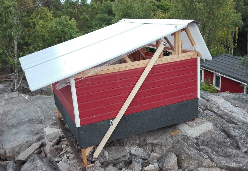
Some people has told me that I must anchor the observatory in the rock, because it can fly away if it comes heavy winds. That is a wise recommendation, because it's my mother in law's house down there, she will not be happy if my observatory crash in her house, then no more stars! 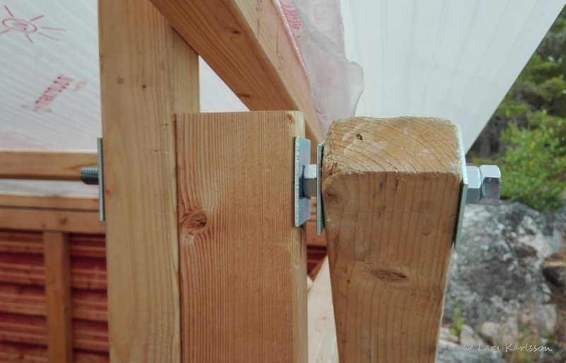
Close up of the upper hinge. 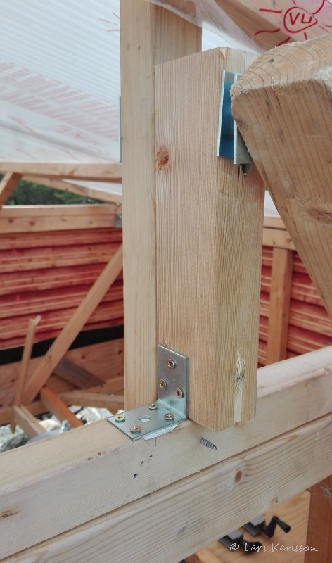
Reinforcement to make it more stable, I need one more up too. 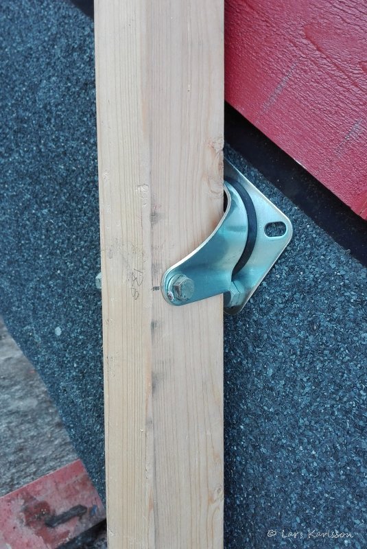
A M8 bolt hold the arm in the lower hinge. 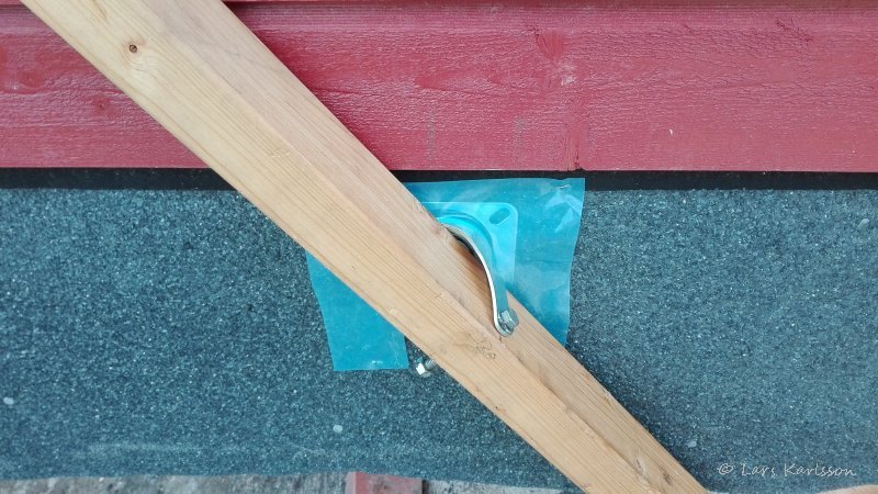
The roller bearing is not very well protected against rain in this position. Maybe this plastic film will help until I got a better solution. 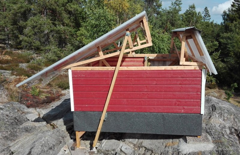
This was a big moment, the first opening of the roof, almost like a "First Light". I had to open the small roof first, then the big roof, when closing, the opposite order. Next step is to have some mechanism on the left side of the main roof. Maybe this will just be a "sliding against a rail" construction, but more elegant will be a second set of arms. I will think about this until next weekend, my construction is very flexible so I have lot of options. When I do next test and open the roof all way out, will the roof's right part clear the wall at left? The heavy steel bar I shall mount on the lower end of the arms. It will act as a counterweight and in the middle of the steel bar I shall have a motor driven threaded rod. The clearance under the observatory is not big, I hope my calculations are correct and it fit. Today the arms are made of wood because it's easy to work with, later maybe they will be replaced with arms made of steel.
|
|