|
Advertisement / Annons: |
3D CAD drawing:
|
Contents:
Note: |
1, CAD design with spiral pattern:Introduction:When I designed a LED stripe holder I faced a new problem, how to design a spiral pattern in FreeCAD. The flat box project: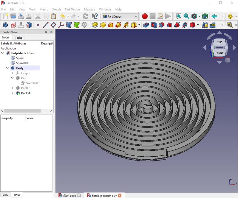
This is the result of my my CAD design of a spiral pattern formed holder. In these groves I will insert the LED stripe. It's open on one side to let the air cool it down. The other side act as a diffuser. More parts will be added later. The road to do this:
There are very good tutorials on YouTube by 'AllVisuals4U' and 'MangoJelly' and some extra help on Wikipedia:
Make spirals: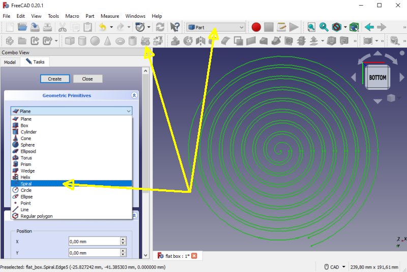
Create two spirals, offset one of them with a bigger diameter. Example: First spiral set diameter to 0 and the other set to 10 mm. This is done i Part mode and the Geometric primitives. Make a Sketch of the spirals: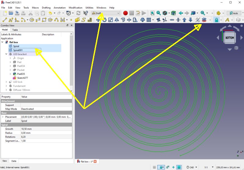
To make something you can draw of the spirals you have to transform the Draft to a Sketch. This is done in Draft mode. Calculation of the spiral:Calculating the length or the numbers of revolution of the spiral. You can use this calculator: Omni Spiral calculator. Or the formula:
W = Width of the spiral, at least 10 mm to not over heat the LEDs ( R2 - R1 ) / W = N2 - N1 = N W*2*PI*( N22 - N12 ) / 2 = L With R1, N1 = 0: R2/W = N W*PI*N2 = L Don't forget to add about 100 mm for the power cable that connect to the LED stripe. The spiral track has to have a width of at least 10 mm to not have the LED to overheat and have free passage to the surrounding air. If it get hot it must have more space and/or a fan. Don't forget the thickness of the spiral walls, what I found 2 mm is enough, with W = 10 mm the free open width will then be 10 - 2 mm = 8 mm. With thicker walls the width, W must be increased. It's tricky tp get the correct size of the spiral to match the LED stripe's length, more trial and error. Move the Sketch to a body: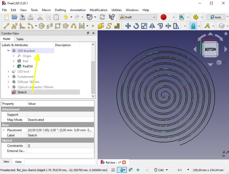
The Sketch is not where you want it. Move it to the body where you doing this. Close the spiral pattern: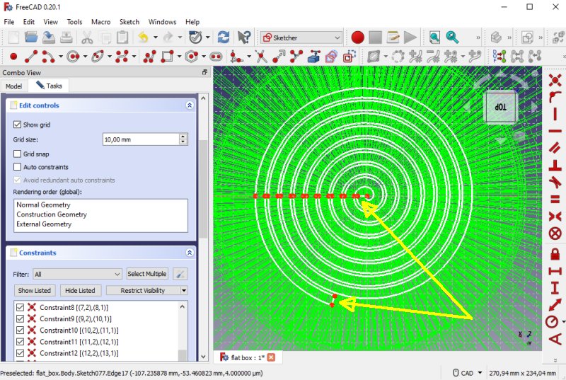
Open the Sketch with the spirals, you have to make the two spirals to a closed figure. Can be a bit tricky to get the line attach to each other. Move the Sketch along an axis: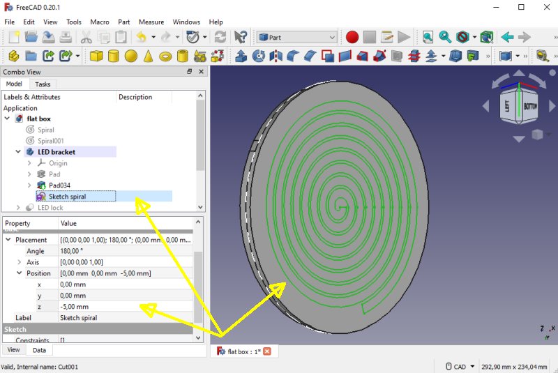
To have the Sketch align to something prepared before, a cylinder in this case. In the Property window, at Base>Position>Z-axis (or some other axis). Move it until it line up where you want it. Make a Pad or Pocket of the spiral and you are finished. If the object disappear when doing this it's probably because of the spiral isn't closed in the step before. 3D-printing of the spiral: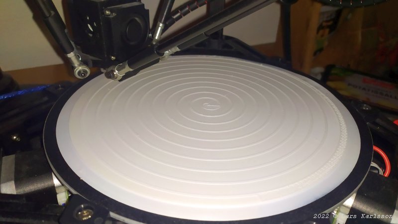
Early in the morning I started the 3D-Printer, it's a 17 hours work. 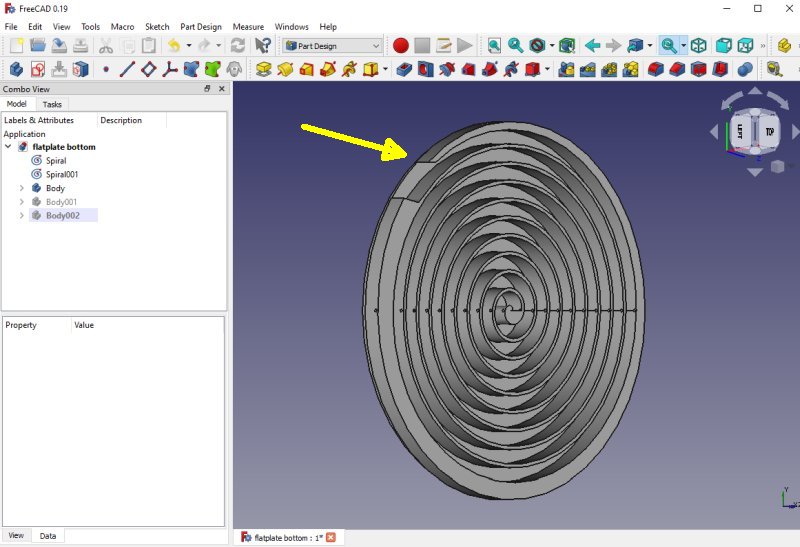
One mistake, the wall was too thin and failed to print, still I can use it as a prototype. Later I make a new design where I make the wall thicker. 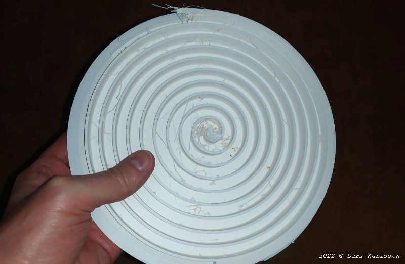
Direct out from the 3D-Printer, the biggest part I ever have printed. 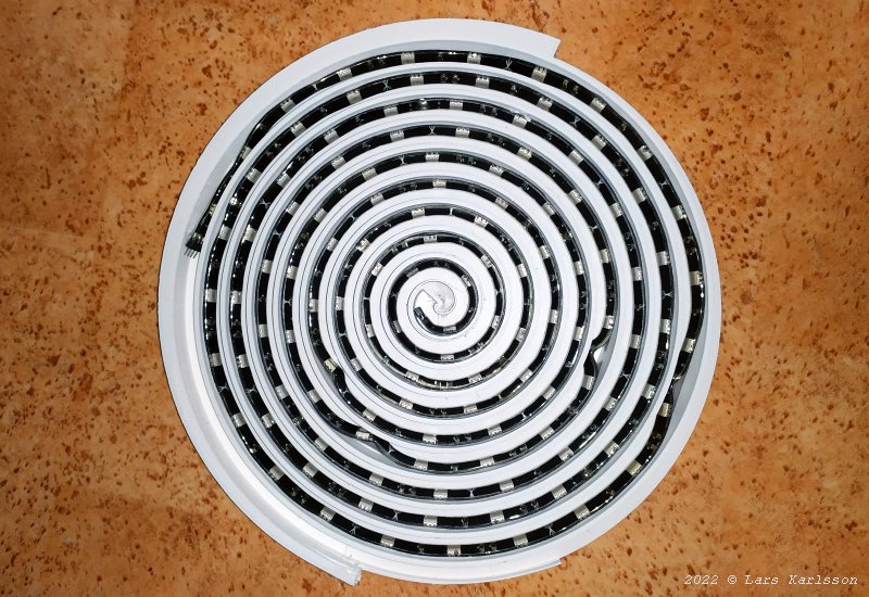
Install the LED stripe in the spiral pattern. 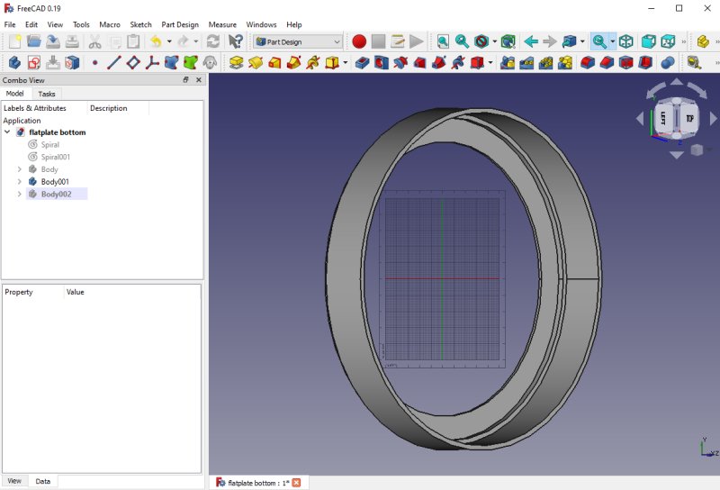
Middle section, here a diffuser will be placed. All the design is done in 'Pad Design' mode, Pads and Pockets. 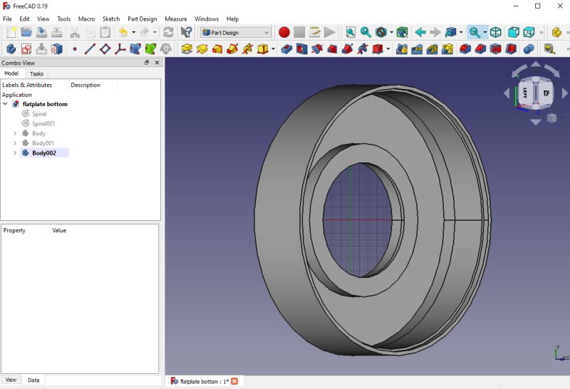
The end section that connect to the camera. If necessary it could be placed another diffuser here. If all these three parts function as I hope I will place them here for download as STL files later. Have a look at my flat image project also: Flat box page. |
|
|