|
Advertisement / Annons: |
3D CAD drawing:
|
Contents:
Note: |
1, CAD bracket for QHY5 camera:Introduction:I have an old QHY5 camera as a guide camera. It work really good and I want to keep it. There are no mount holes on this camera and I have to make some bracket for it. At the same time I want this bracket to hold the the USB Hub. QHY5 camera and its Tokina lens: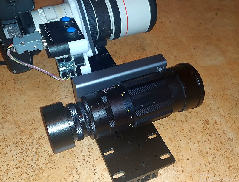
To the QHY5 camera I have attached a Tokina 200 mm f 1/3.5 lens. The bracket to the camera I plan to design as a tube ring and to the lens an ordinary tube ring. The USB-Hub: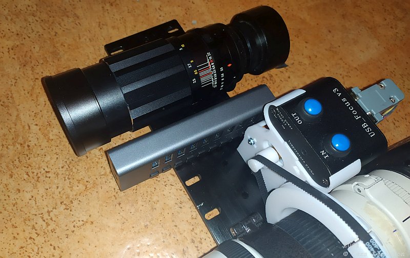
The new USB-Hub I bought is huge, I need something to hold it in place. I will do an attempt to use the same bracket to the camera to also hold the USB-Hub. Very narrow space here and a lot of USB cables to connect. FreeCAD, 2D Sketch: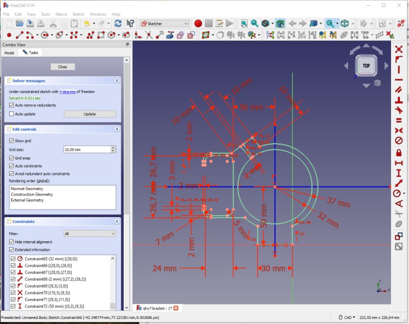
The ring at the center hold the camera and the open bracket to the left hold one end of the USB-Hub. When a line is green it is constraint, it can't be moved. Here are all of them green, they are locked in its position. That is what all the red constraints do. The 3D designed bracket: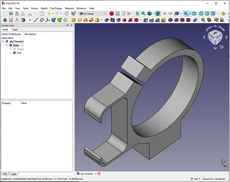
After the 2D sketch is finished I pad it out to 15 mm. Notice that I this time I did the slit in the 2D Sketch, not as a subtraction of a rectangular block. Add a hole: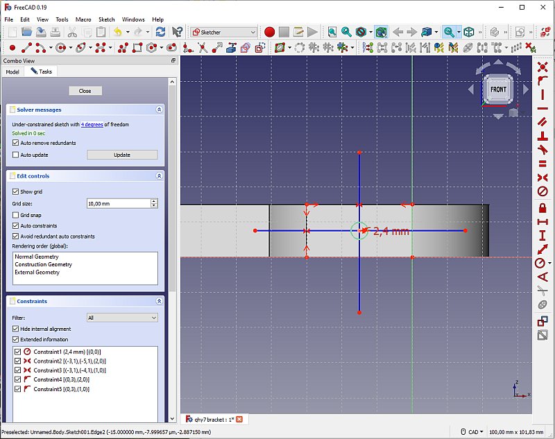
I "Drill" the hole that hold the bracket to the dovetail, I also for first time make the threads, M6, in the 3D printer. Could it really work ? No, I had to thread it afterwards. 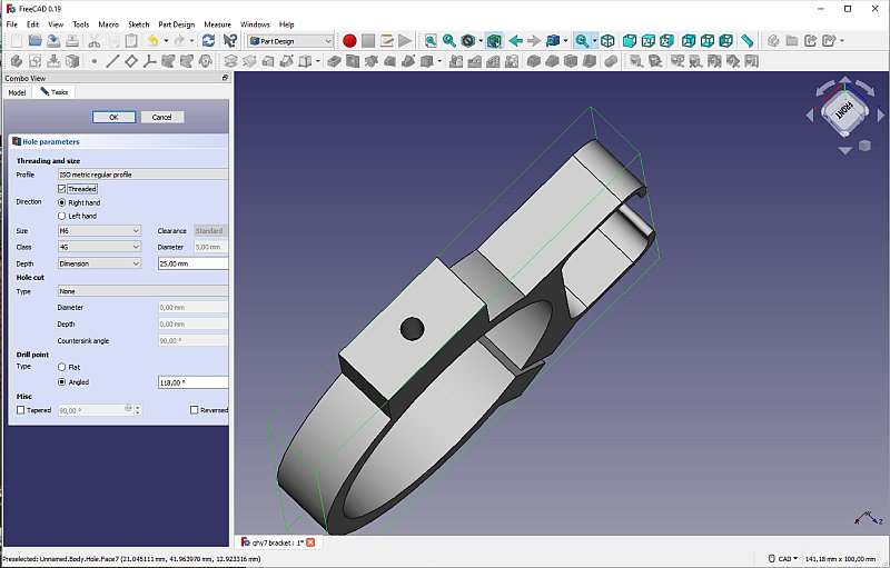
Setup the hole parameters for a M6 threaded hole. Very convenient, if I want it left hand threaded I don't have to buy new tools, just a click. The slit clamp: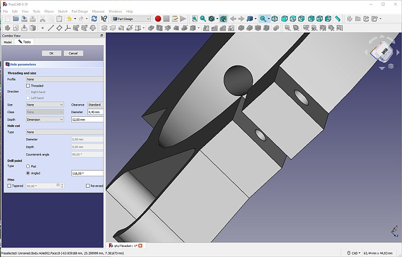
Holes at the slit for the lock screw. Same procedure again, but now I stack two holes on top of each other, the lower smaller hole will be threaded later. Stop block: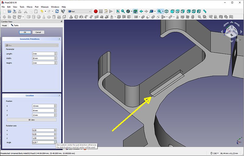
In Part mode I add a rectangular block, this will act as a stop for the USB-Hub to not let it slide out of its holder. X-ray along Z-axis: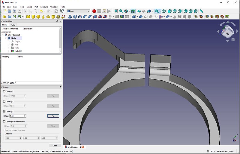
With the Clipping toll at tab View I check that the hole is in its correct position. Add info text: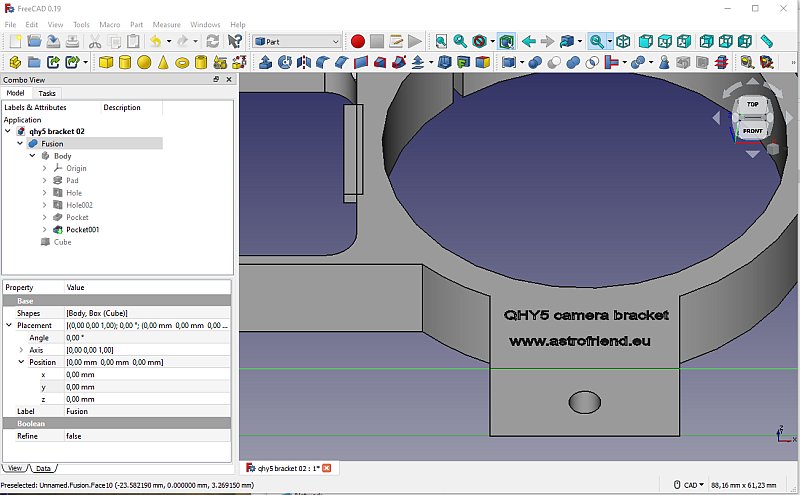
This was a big mistake, I placed the text towards the printer bed. The surface at this side is very rough and the text will be hard to read, and even worse it did the 3D-printer to failure. Round edges: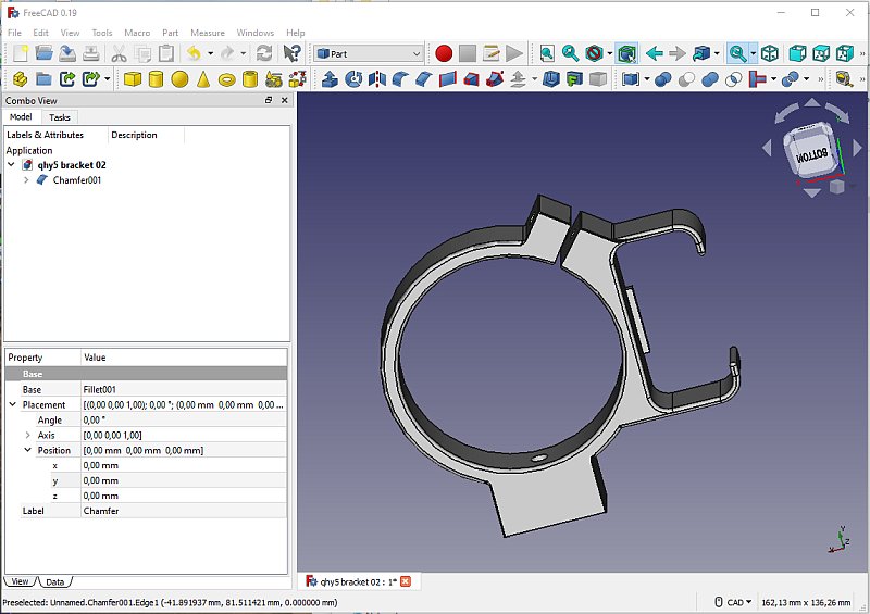
At last, add rounded edges. Maybe this function is a bit buggy, it often cause me problems. |
|
|