|
Advertisement / Annons: |
3D CAD:
|
Contents:
Note: |
11, CAD of 174 new version, part 6:Because of the problem I had when printing the first version of the 174 teeth pulley I had to take a step back. The problem was that it added a second bottom plane halfway up the Z-axis. I must figure out what was wrong, I'm sure it had something to do with my drawing. I solved it after a while and here is the new version of my CAD. I also want it more flexible, I don't want to reCAD everything from scratch when I make a new version. New pulley with different start: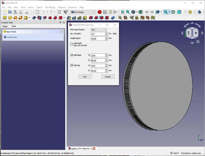
This time I start with a more basic pulley, no center hole and only standard flanges. 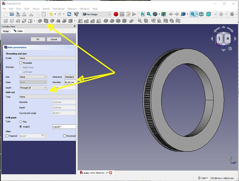
I also go direct to Part Design and use the hole tool. No intermediate steps. 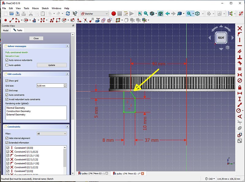
This is totally new. I make a new 2D drawing in the YZ-plane, use the Sketcher mode. My plan is, if I change the parameters here the whole pulley will by automatic redesign. Click close when finished. What's important if you want to print an object without support is that no angle are less than 55 degrees. In this case the angle (where the yellow arrow point) is 59 degrees or 149 degrees from the vertical plane. 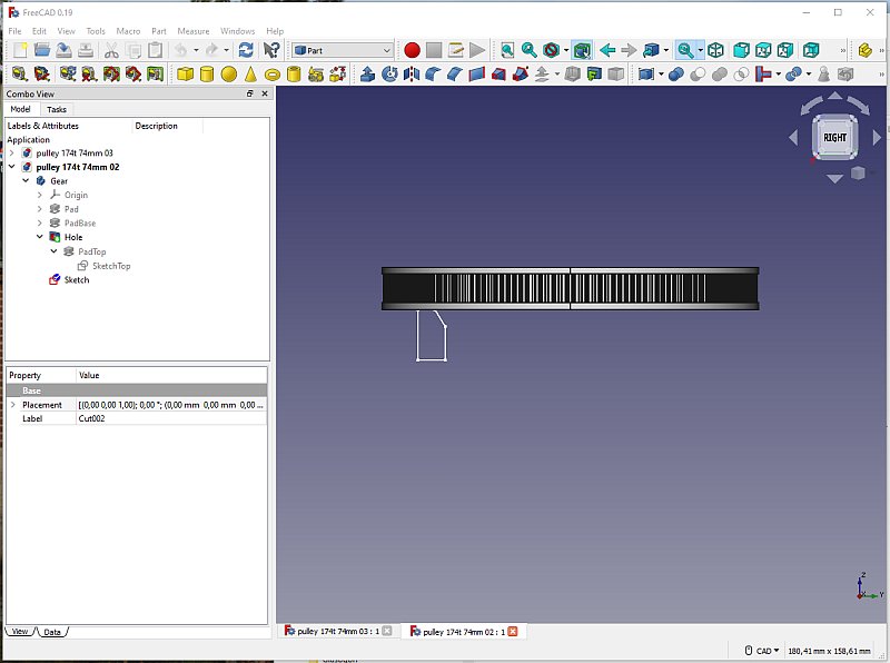
Important to have the 2D drawing in correct orientation, in this case the YZ-plane. It took some time to solve that. 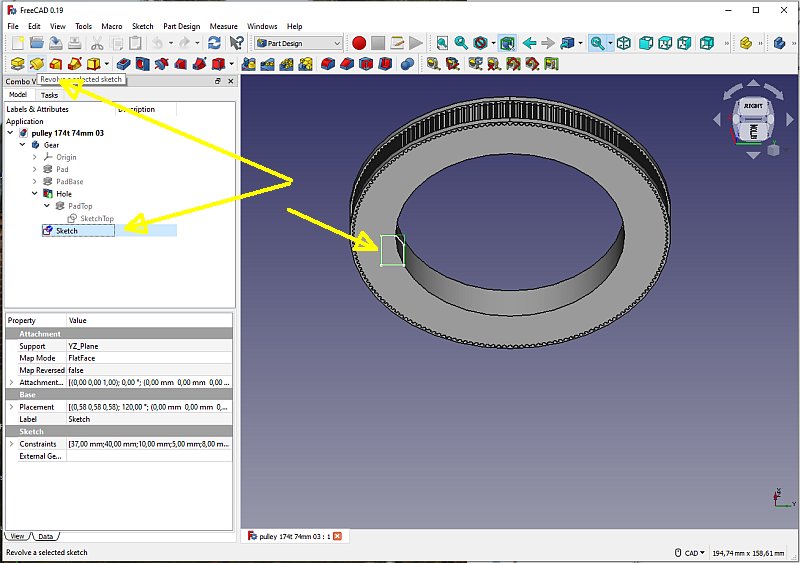
The small rectangular drawing will now be rotated around the Z-axis with the Revolver tool. 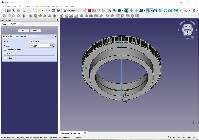
So much simpler to do the drawing with this technique and it's easy to change too. 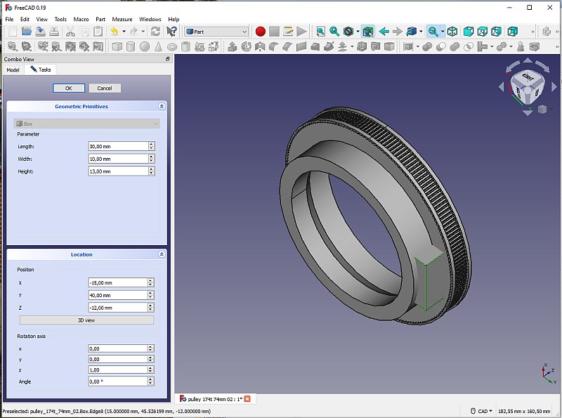
I add the rectangular block as earlier. 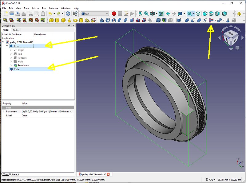
Now the part that I missed earlier and cause the printer to print a second bottom plane halfway up along the Z-axis. The drawing consist of two main blocks. I must join them together to get rid of the inner walls. Mark the two drawings and use the Join Wallet Objects tool, this is done in the Part mode. 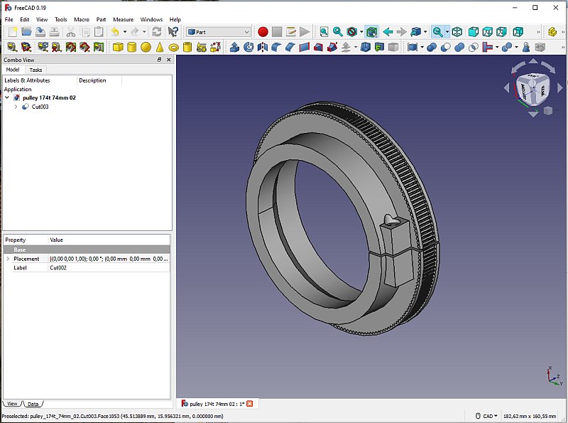
Added the hole as before, increased the hole diameter from 4.2 mm to 4.5. The slit is also added, 1 mm as earlier. I was surprised that I could bend the pulley and open the slit to 12 mm without the pulley broke apart. 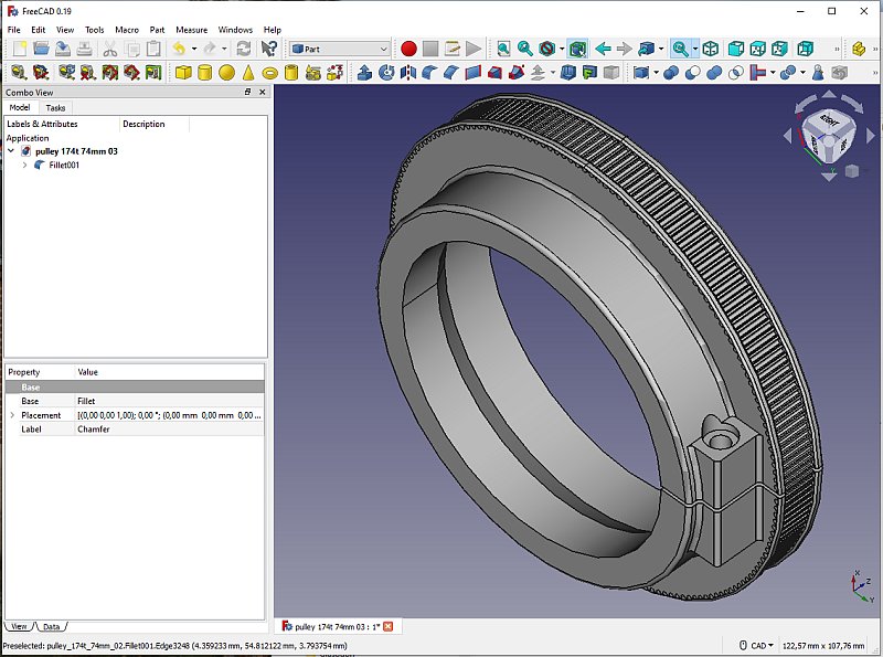
Round of the edges as before. Save the file (and lot of intermediate files) and Export a STL file for the slicer software Cura. |
|
|