|
Advertisement / Annons: |
3D CAD:
|
Contents:
Note: |
10, CAD of 174 clean from support material, part 5:When it was printed I noticed it has supports at a lot of places that's not needed. Must be something wrong in my drawing. Inspection of the pulley: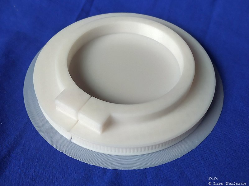
It looks very good and all dimensions are what I had designed it to be. But in center is a massive flat surface. It should be a big hole in that place. 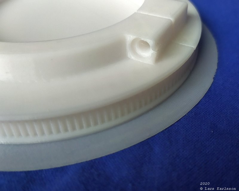
Hole to the lock screw. 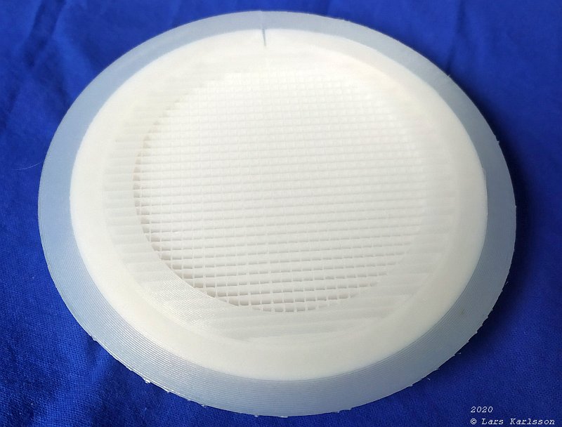
Backside of the pulley, the raster is the support that has built up. 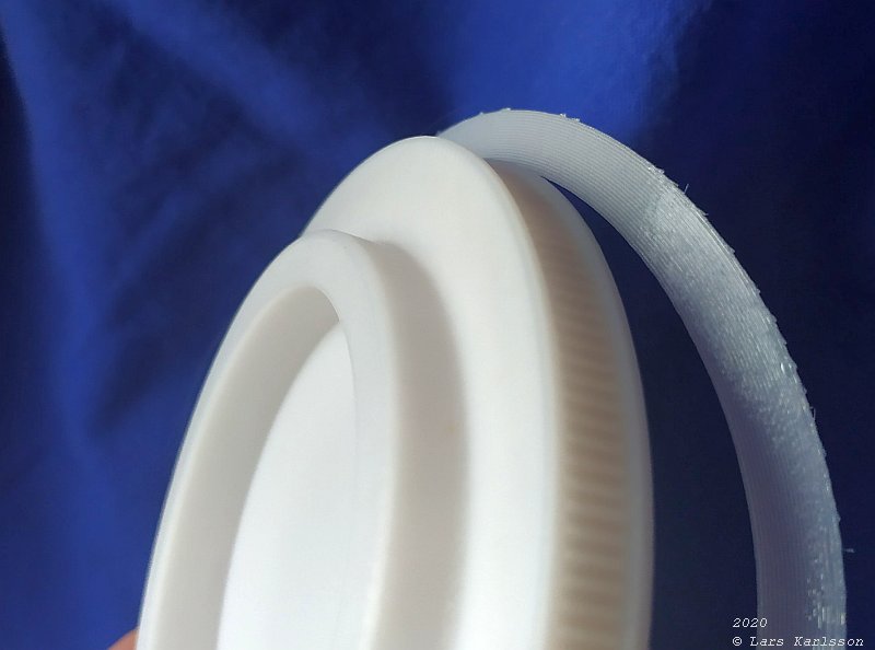
The outer ring is easy to brake off, it was only used to hold it against the printer bed. 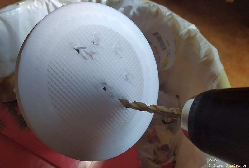
Normally it should be easy to brake off the support material, but in this case it added a massive 2 mm surface on top. 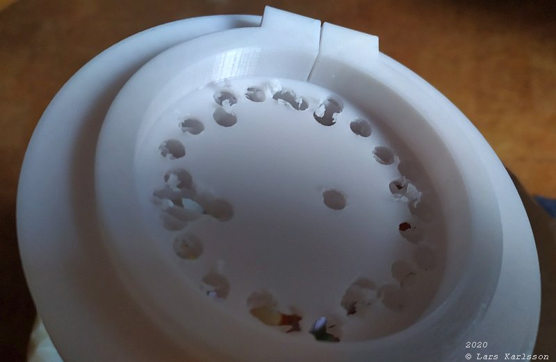
I made a lot of holes in a circle around the rim. 
The massive center surface that shouldn't be there. 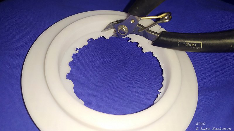
More brutal force. 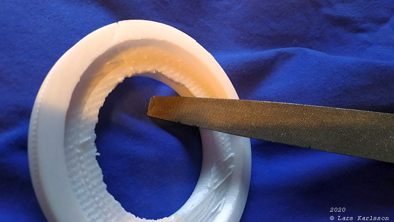
And at last, some fine trimming, the surface look ugly but otherwise it looks okay. 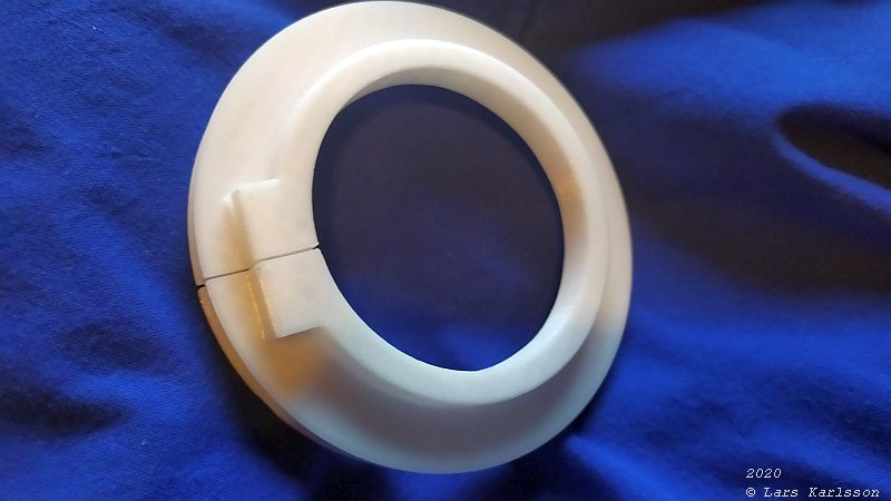
After a massive work it look like this. 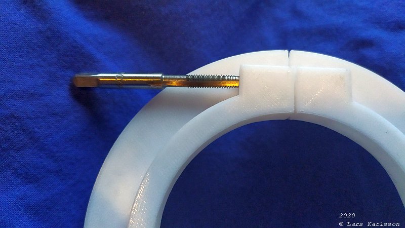
Thread of M4 for the locking screw. 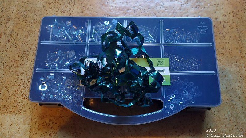
A Christmas present from my mother-in-law, a box full of screws and nuts! 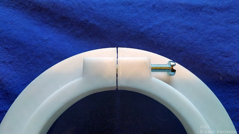
The M4 screw fit, but I need to drill the hole to 4.2 mm even if it was already in the drawing set to that size. 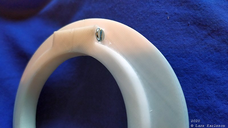
Looks more professional when letting the screws sunk into the material. 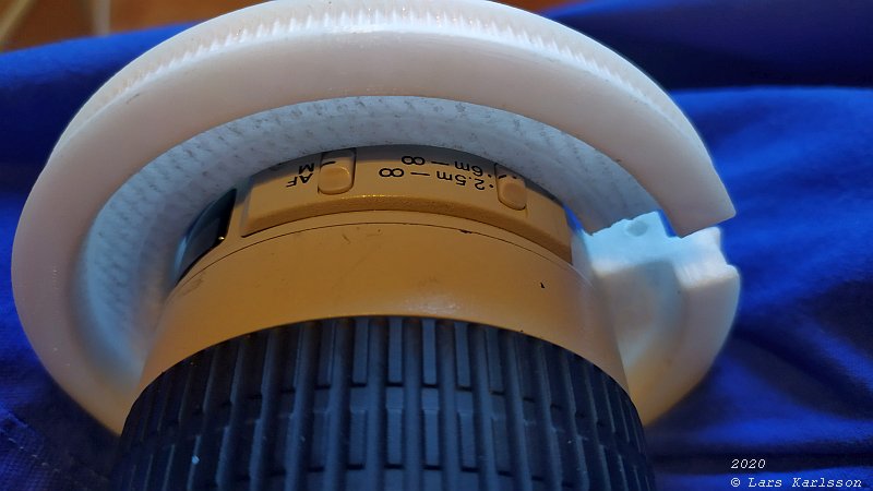
When attaching the pulley on the lens I found the buttons protruding and got a little problem. I expand the slits to 12 mm and after that it slide into its place. Now I noticed that the inner diameter I made was for another lens. No problem with that, I can use this pulley for that lens. But now I want a pulley that fit my Canon 300 mm lens, and also another lens, the Pentax medium format lens. I have to find a better way to make the drawing more customizable. Mass production, and I have an idea how to make the drawing to do that. |
|
|