|
Advertisement / Annons: |
3D CAD:
|
Contents:
Note: |
4, CAD of 15 teeth pulley, part 3:This hole is even more difficult to make because it's perpendicular to a curved surface. Making a hole to the lock screw:This was complicated, much easier of course to drill the hole after it's printed. But better to learn how to do this for the future. 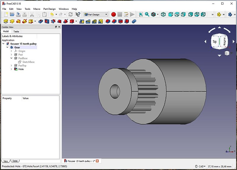
To lock the pulley to the shaft I need a lock screw. 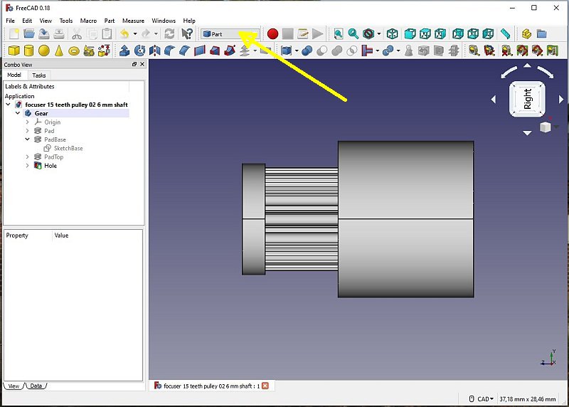
Orient the pulley along the Z-axis. We have to make a hole through the curved surface. I couldn't find how to make a circle on a curved surface. I do it with another method, the subtraction method. Switch to part Mode. 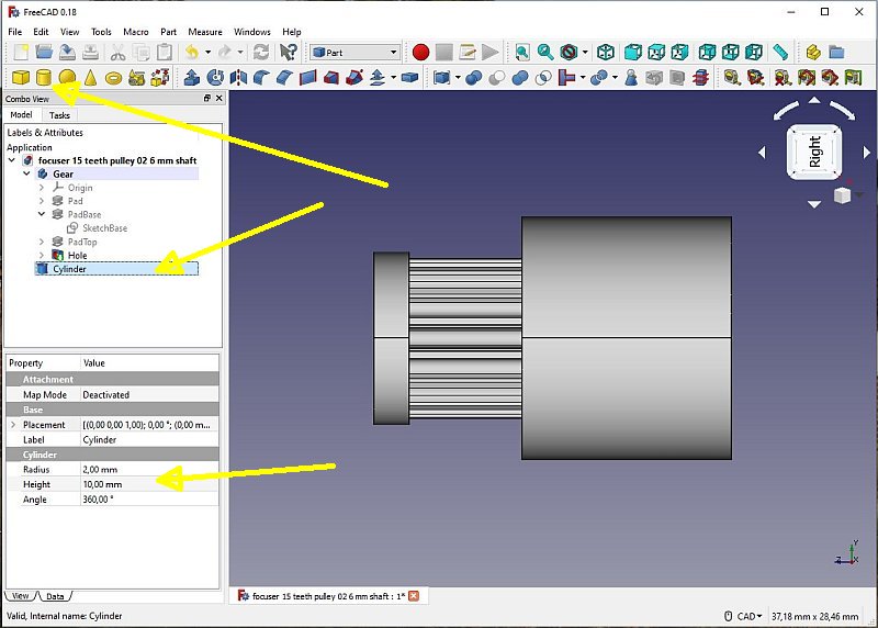
Make a cylinder, 10 mm long and with a radius of 2 mm. But where is it ? 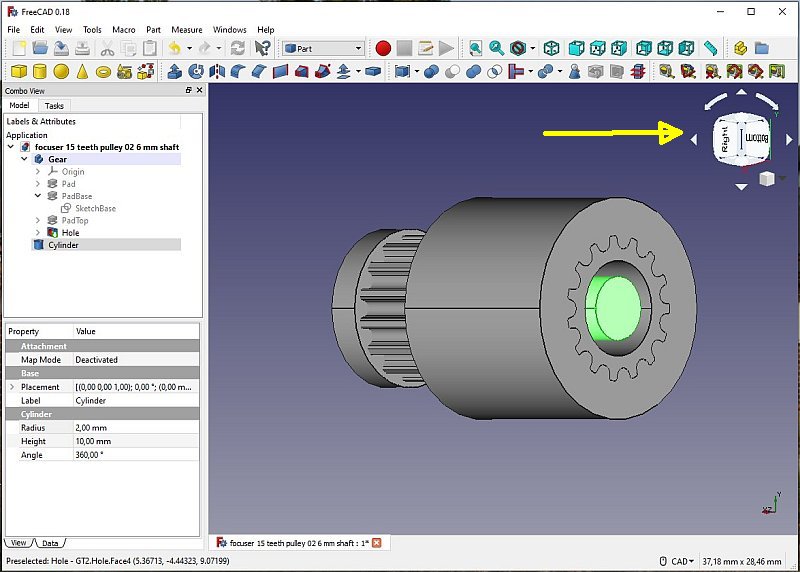
Rotate the pulley 45 degrees, and there it is, inside the pulley. 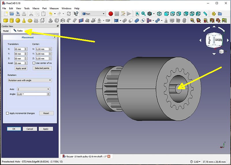
Change the radius to 1 mm to have a hole of 2 mm diameter, for a threaded hole, M3 the hole diameter shall be 2.5 mm. I didn't trust the precision and I drill it from 2 to 2.5 mm later and then threaded it. With the cylinder it the menu to the left marked, switch over to Task Menu. 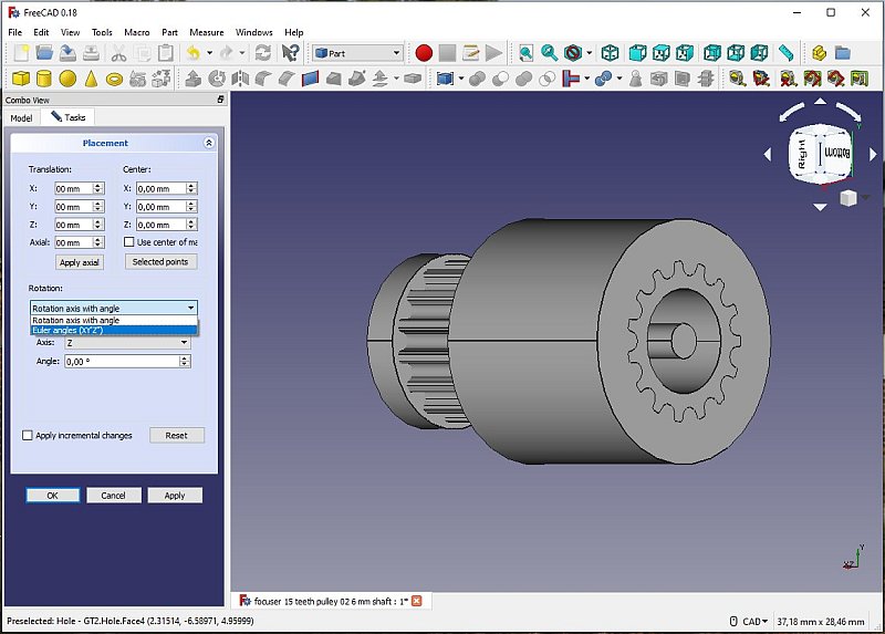
Change the Rotation option to: Euler angles XY'Z". 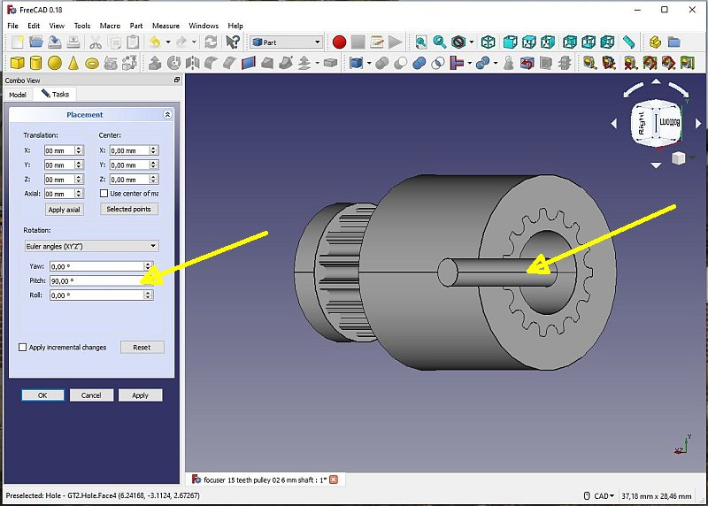
Change the Pitch to 90 degree. 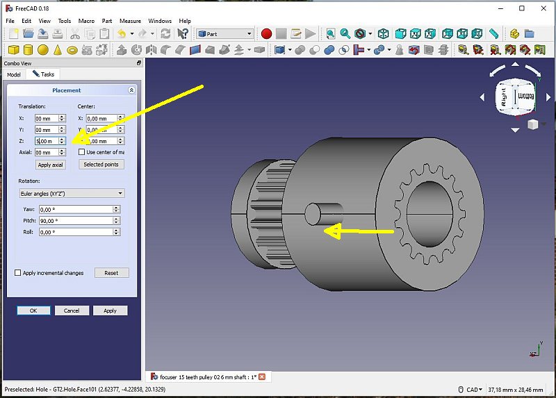
Translate along the Z-axis 5 mm. 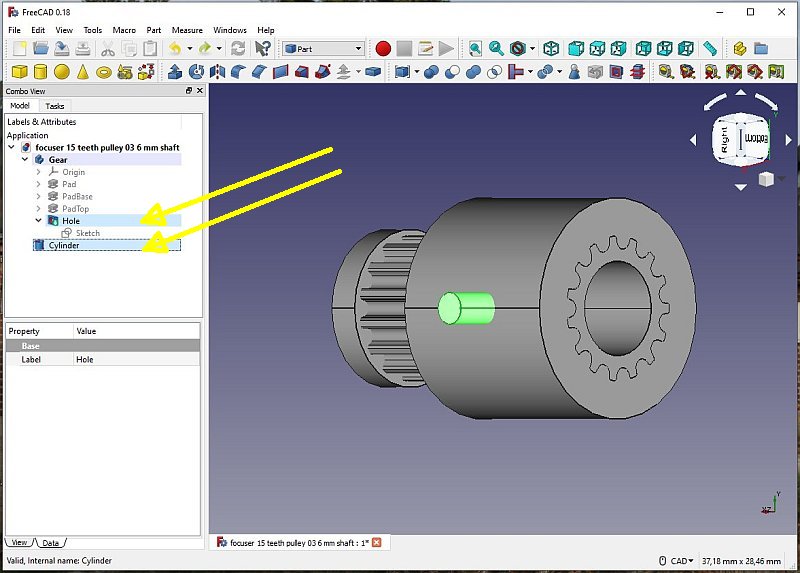
Mark Hole and Cylinder (hold down the Ctrl key). The order you click them decide which of them that will be subtracted. 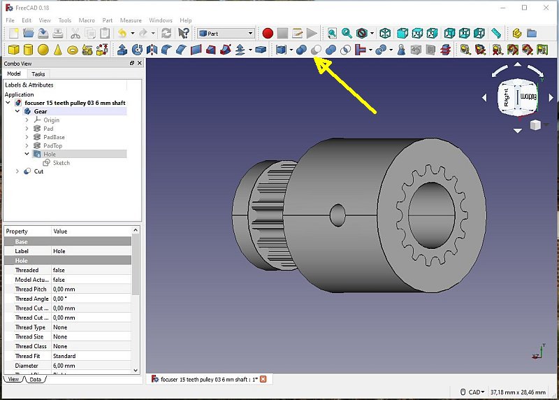
Click on the button: Make a cut of two shapes. We have a hole perpendicular to the Z axis. |
|
|