|
Advertisement / Annons: |
My astronomy project:
|
Content:Implement of external push pull screws:
Related projects:
Note: |
1: New design with Push Pull screwsI just felt that my earlier idea with 3D-printed new chassi for the focuser will not work. I put too high demand of the 3D-printed plastic parts. And I also want to get rid of the gearbox because it can introduce backlash. Now I have started on a new design where I keep the original chassi in aluminum. I replace the friction coupling with three (later just two) screws that pull and push on the focuser draw tube. Much easier to make and no need of the gearbox, just enough with a small reduction that will be done with the timing belt gears. First design with three push pull screws: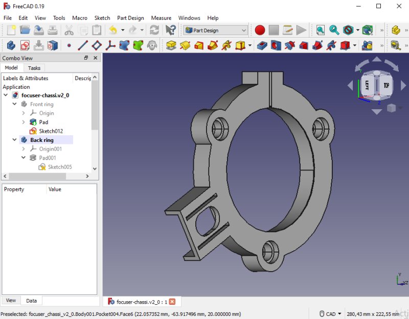
This part will clamp around the focus chassi at the telescope end. It also hold a NEMA 17 stepper motor. The three holes will hold 6 thin roller bearings, size 12x21x5 mm. 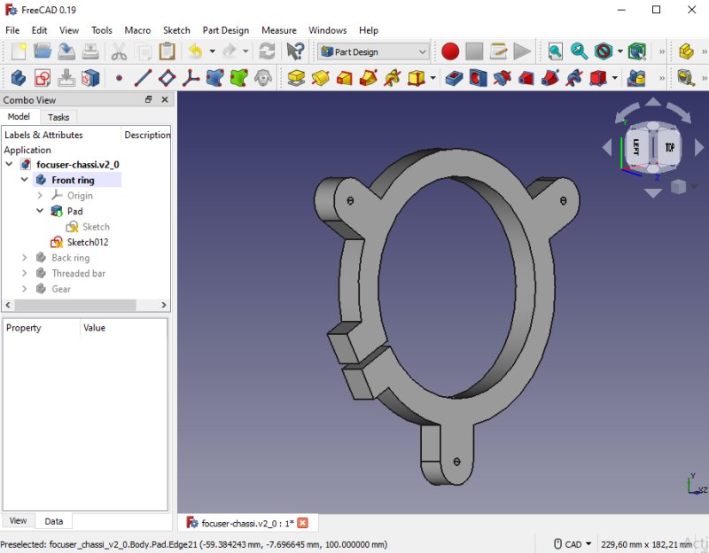
The other bracket will clamp around the focus tube drawer, the camera end. The three small holes will be threaded M4 and hold the long screws that push and pull the focuser drawer back and forth with the rotating nuts. 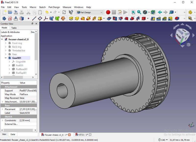
Three M4 nuts will be controlled by the timing belt gear. When a M4 screw rotate one revolution it moves 0.7 mm. That's the main gearbox in this case. If the nut is direct driven by a 200 step motor each step move the focus 3.5 my. The gear is a 40 GT2 teeth gear, later I changed it to 60 teeth. How I design the pulleys: GT2 pulleys in FreeCAD. 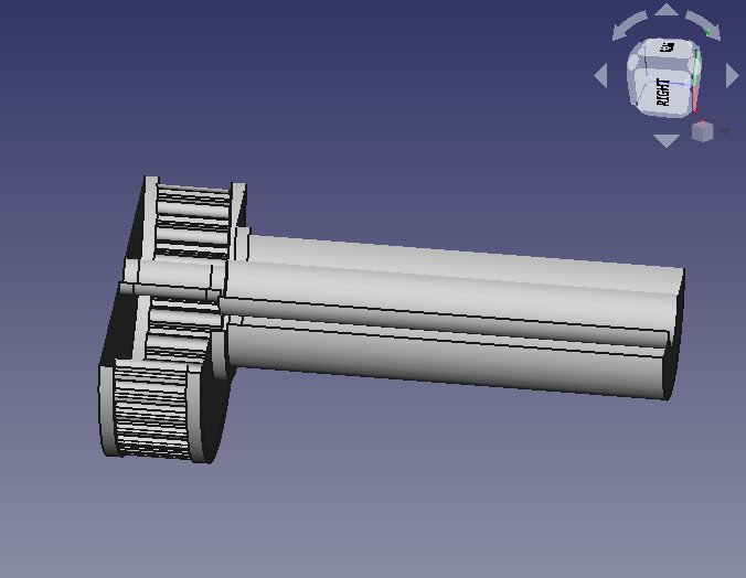
The left most 10 mm is threaded for M4, the right part is open where the screw bar goes out. I start to thread it direct in the plastic, if it doesn't work well I find another solution. It's made for a 6 mm wide GT2 timing belt, better had been 3 mm but I couldn't find any. 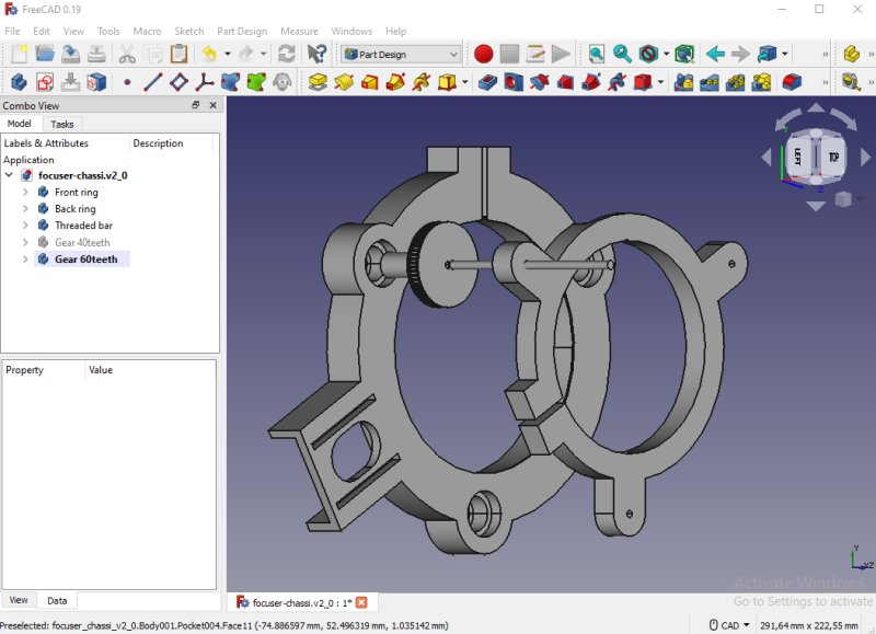
The four parts in place, there will of course also be another two screw bars and M4 timing belt gear nuts. 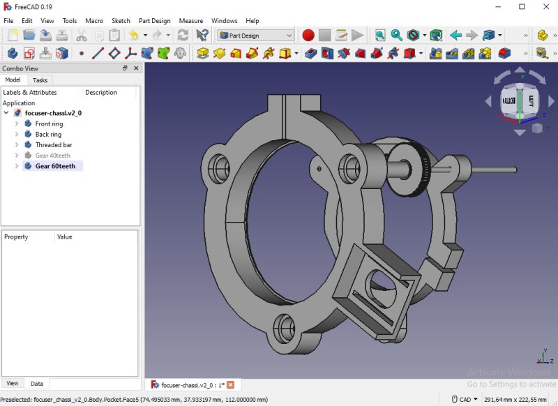
From the telescope side, the NEMA 17 stepper motor holder, it's adjustable +/- 5 mm. The focus drawer tube can move 100 mm, I don't think I can use more than 60 mm of that. The protruding screws will hit the telescope if I use the full length. When the telescope is pointing to the zenith it has to lift 4kg, to that the friction must be added. The NEMA 17 stepper motor I choose has a lot of torque compare to my earlier focuser motor which was too weak. I don't have the data of this stepper motor, but normally they have a holding torque of 20 N/cm (0.2 N/m). Without friction and coupled to a M4 screw (act as a 100:1 gearbox) it should have a lift capacity of about 50 kg. I know the friction in a screw is high I but don't how much, 50% ? Strange figures, maybe I did some error calculation. Here are my focuser calculators: Focus depth and Focuser gear ratio 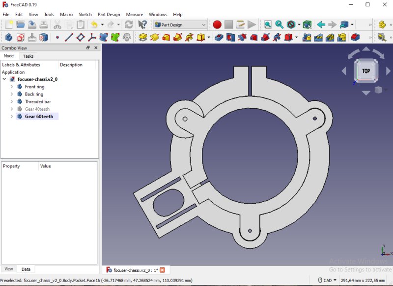
View from the camera side, one problem is to have the timing belt not hit any other parts. One reason why I have to increase the size of the gears. 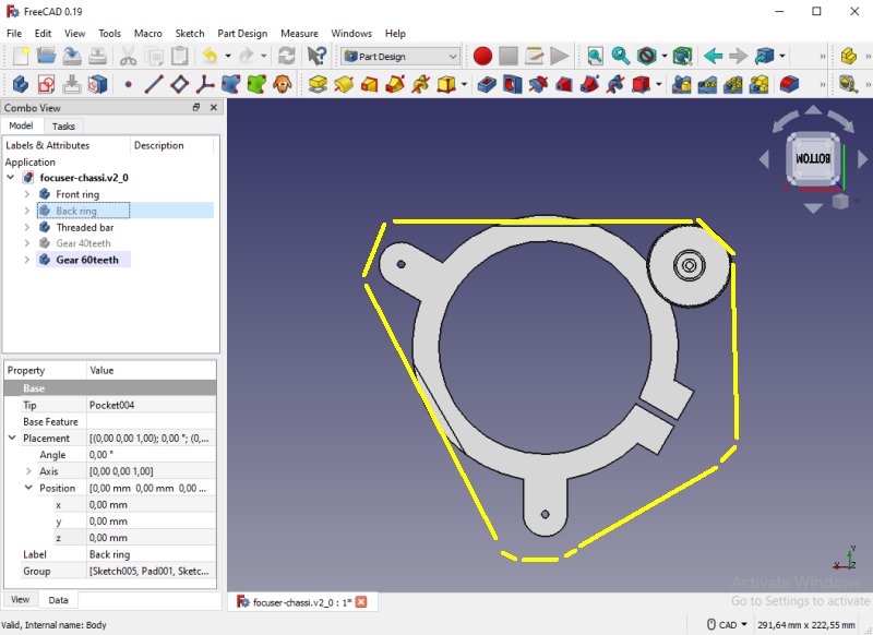
The yellow line is how the timing belt goes around the three gears and the stepper motor gear. I have made two pockets in the clamp ring to have the timing belt not hit it, even the gears needs it when focus is at zero (full in). 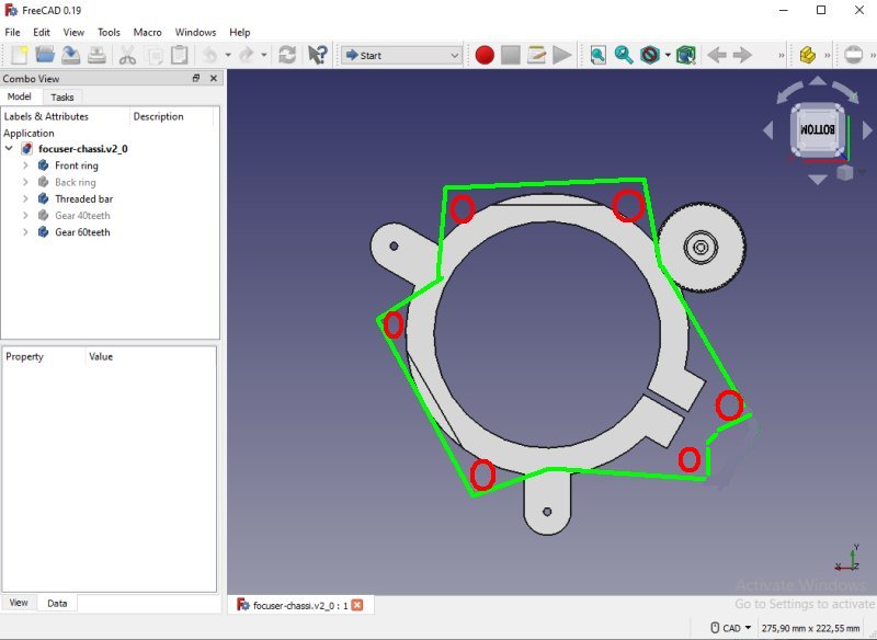
My friend gave me an interesting idea. I could invert the timing belt and have six free rolling supports for the timing belt. With this I can reduce the size of the gears and it will give more contact between the gears and the timing belt. The drawback, more parts that can flex and more complicated. From three to two push pull screws: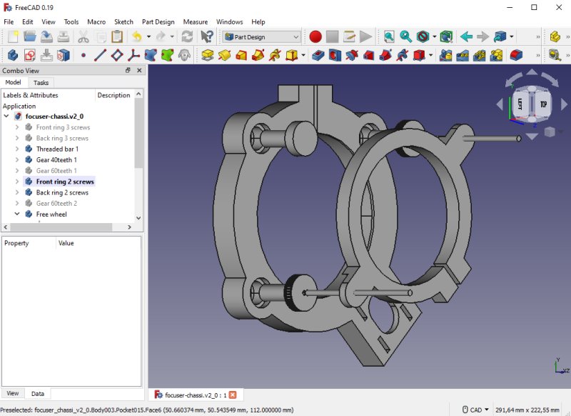
After a long time thinking over the problem I did a new design with only two screws and a free wheel. 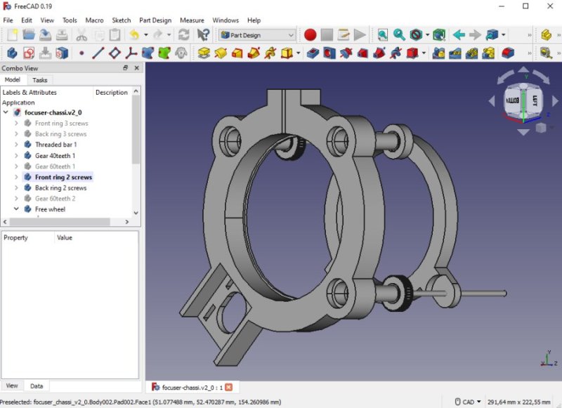
Now there will be no problem that the timing belt hit anything and it's not complicated to build. 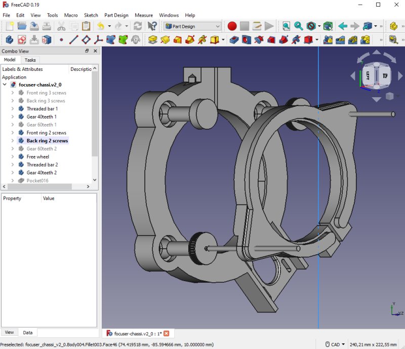
Some more fine adjustments. Moved the NEMA 17 motor back 10 mm. Reinforced the right clamp ring, I don't want any flex in it. 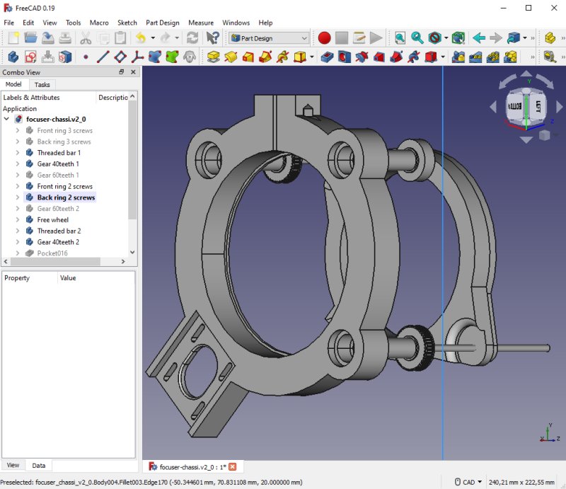
This side is where the NEMA 17 motor will be placed. This is a heavy and high torque NEMA 17 motor, later when I finished I'm sure that I can reduce the size of the motor. The M4 rods I plan to have in stainless steel, less dependent of temperature variations than brass. If single step is to coarse I can change to a 0.9 stepper motor, I can also reduce the gear ratio to 2:1, then I get more torque also. As it's now the full stroke is 160 mm, so a 2:1 reduction will be good, with one of the mentioned solutions. It could be achieved also by replacing the M4 rods with M3 rods.
|
|