|
Advertisement / Annons: |
My astronomy project:
|
Content:Implement of external push pull screws:
Related projects:
Note: |
4: Assembling the Push Pull system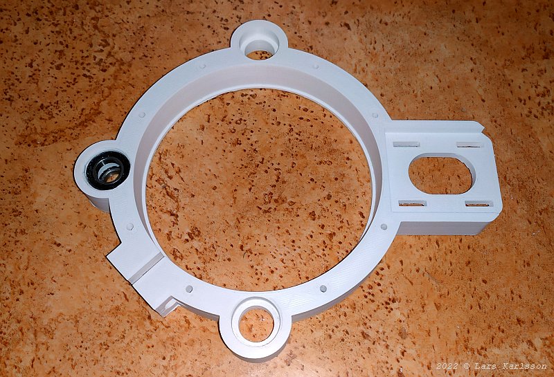
After waiting many hours until the 3D-printer finished the job I got this. It's the back clamp ring. I had to grind the holes for the roller bearings a bit, but not much. 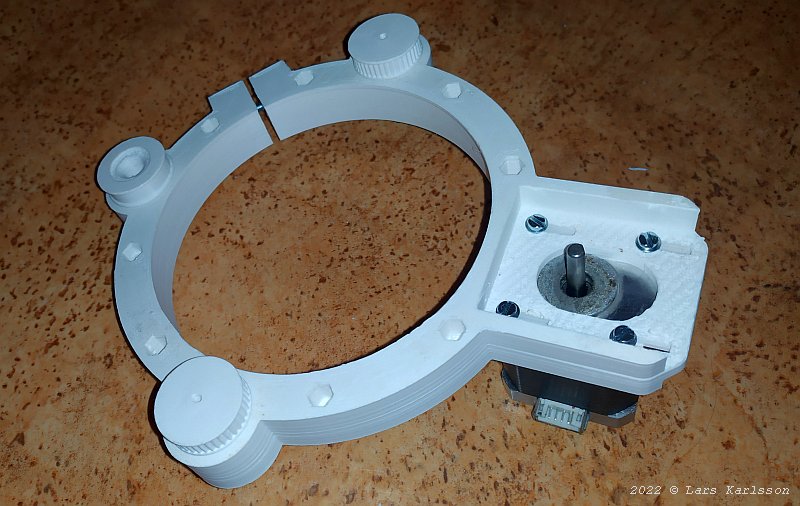
Now with the timing belt gears and stepper motor installed. The motor is in its inner position. 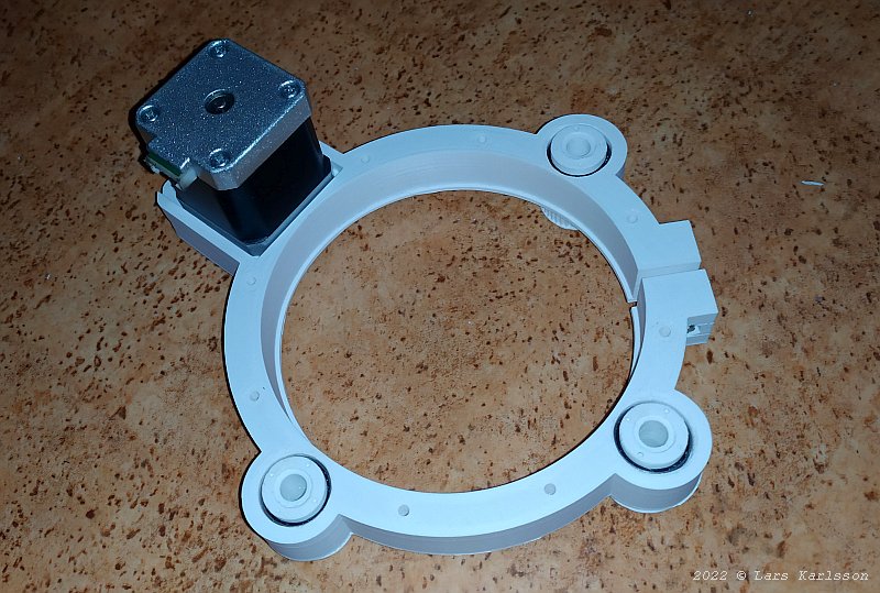
From the backside, it's here the M3 threaded rods will come through. 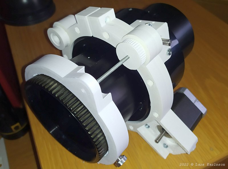
The M3 screw rods is locked at the front ring clamp (left). When the timing belt gears rotate with its nut they push and pull on these rods, the focus move. Now in the outer position, at most I can reach the outer focus position at 65 mm. 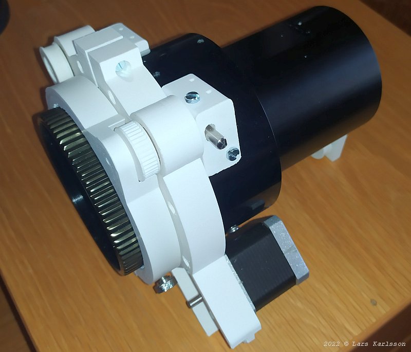
Zero focus position, altogether it doesn't take up very much space. The earlier focus motor extended far away from the telescope too. 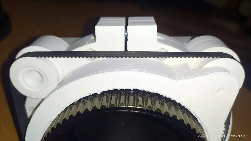
It wasn't so easy to have a clear path for the timing belt. 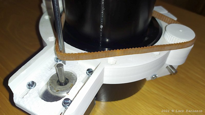
Now I must decide if I want a half or full steps driver. When I know that I can calculate the timing belt gears ratio and design a gear for the stepper motor. 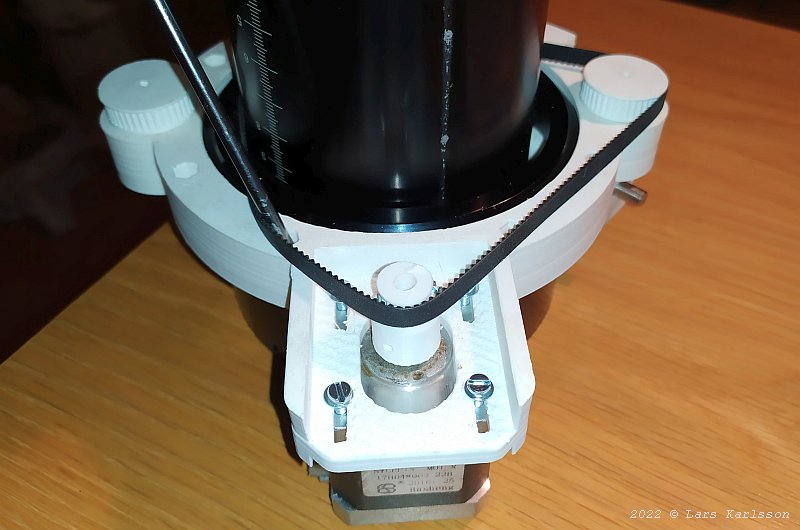
For full step mode I calculated for 70 mm usable stroke length a gear ratio of 2.34:1 is needed. One of the gears has 40 teeth, then the stepper motor teeth number shall be around 17 teeth (in half step mode 34 teeth). It's not good with too few teeth, the timing belt has to wrap around the gear in too small diameter. I choose to design a 20 teeth gear, the resolution will be 1.25 my and the stroke 82 mm (65536 steps) with that gear. I used my own focus calculator to find out this: Focuser gear ratio . I used the Rack & Pinion setting, 70 mm stroke, 140:1 teeth (M3), no micro step. I must also look for what timing belt length are available, it has been difficult earlier to other projects to find the correct dimension. An estimate is that a length of 490 to 505 mm will be correct, with a pitch of 2 mm it will be 245 to 252 teeth. I can adjust the needed length by moving the stepper motor in and out, if that isn't enough I can also change the diameter of the opposite free running wheel. I found one timing belt with the length of 496 mm and have order it, we will see if it fits. Installing push pull screws: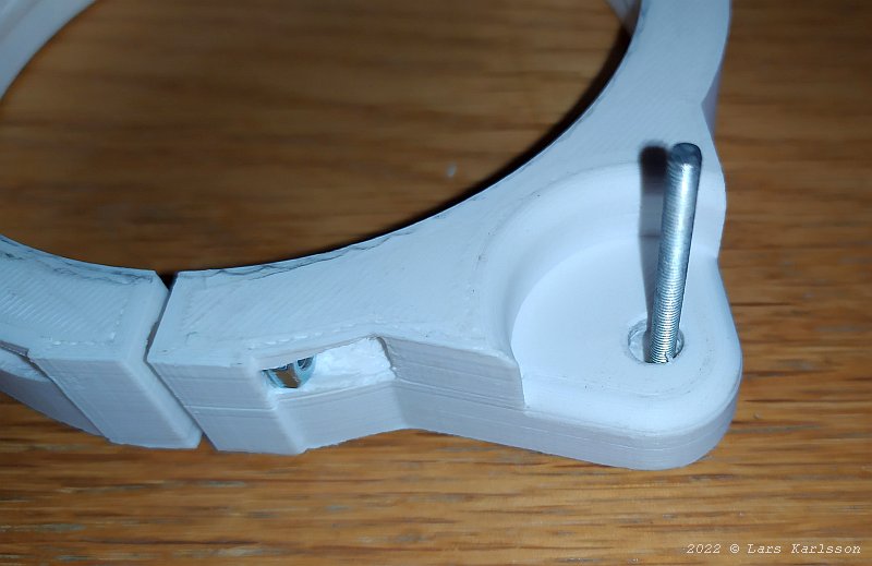
I have came so far now that I can install the M3 push pull screws. My original plan was to have the holes threaded, but I got problem to have them centered around the rotating gear's M3 threaded hole. I have to drill the hole 6 mm and can now adjust it exactly in center of the nut. These screws are short and only for testing purpose, later they will be replaced by 90 mm long screws. 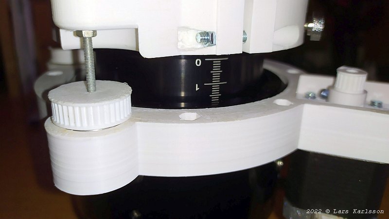
When I added the nut I must also make space for it, I have to separate the front and back ring by 4 mm. Later I can make pockets in the timing belt gear where the nuts can slide in. 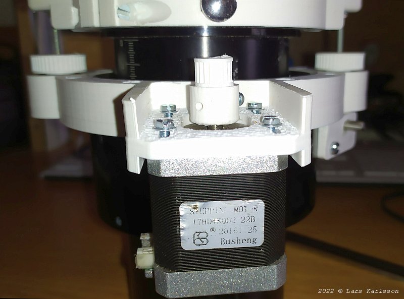
The two push pull screws are 180 degrees apart. They must be synchronized to not put sideway force to the focuser draw tube. 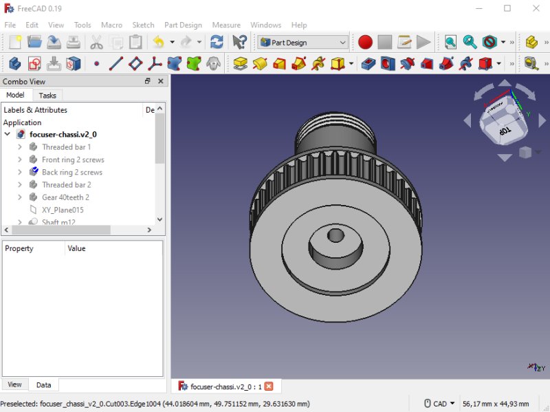
The new gear with a pocket where the push pull screw's nut and washer can slide in. At the same time I change the length of the M3 thread from 8 mm to 18 mm to have it more strong. Installing timing belt: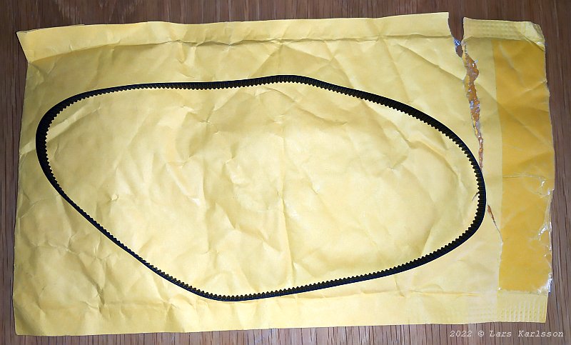
In the middle of the night something dropped down the mail box. I didn't know what it was until I opened it. It was the new half meter long timing belt I ordered. 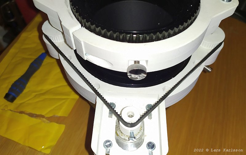
Early in the morning I installed it to check if I ordered the correct length. It fits perfect but no extra if I need to increase the size of the gears. 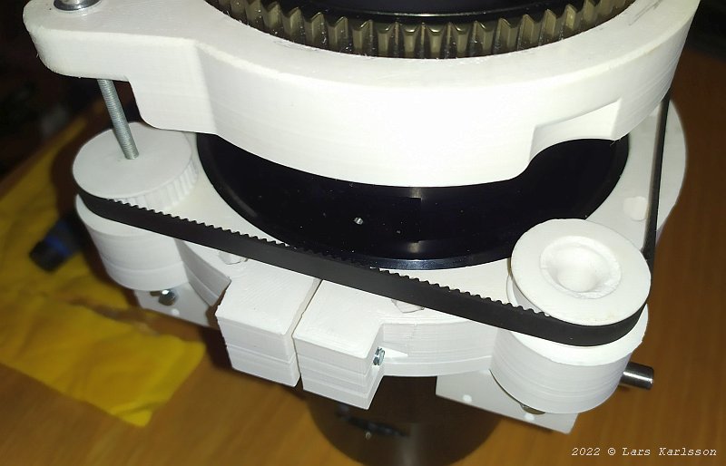
On the backside where the free running wheel is placed. I can reduce the size of it and gain some millimeters, but not much. But very satisfied with this. 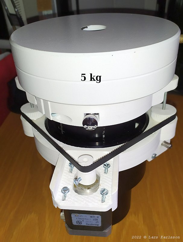
I did a test load to verify that it didn't fall apart. Placed a 5 kg weight on top, to that I had to add the focus drawer tube weight, together about 5.4 kg. The plastic didn't brake and I didn't need much torque to rotate the stepper motor shaft. In the beginning the load will be more like 3 kg and not always pointing to zenith. I think the big problem will be the plastic threads worn out, but I have a solution for that. Now it's time to plan for a hard ware driver to the stepper motor and it must be compatible with INDI drivers. Have a look at project page were I have started to draw plans: Stepper motor driver .
|
|