|
Advertisement / Annons: |
My astronomy project:
|
Content:Ideas about 3D-print rack and pinion gears:
Related projects:
Note: |
1: 3D-Printing Rack & Pinion gearsAfter a lot of different attempt to fix the friction coupling with its slipping problem. The friction coupling is more to visual observations, with heavy camera and other equipment the friction coupler is overloaded. I solved it earlier with a higher setting of the force to the friction shaft, but then the stepper motor get in problem to handle the higher torque. Now I do something more radical, 3D-printing a rack & pinion gear box ! 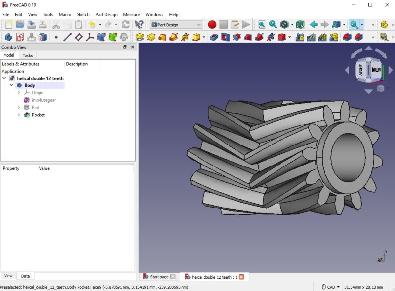
I start with a drawing of the pinion gear. One importing thing is to have the rotation smooth, to handle that the teeth is in an angle, 40 degrees. But this can cause to focus tube to rotate, I draw the gear with a double helix where the second one is inverted. You have to addon the Gear module to FreeCAD to do this kind of drawings. You find it under the Tools menu. More information about the FCGear Workbench:
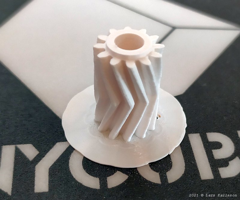
It only took 25 minutes to print this helical gear, it is 20 mm wide and has twelve teeth. The module is 1 mm. It looks very good to me. 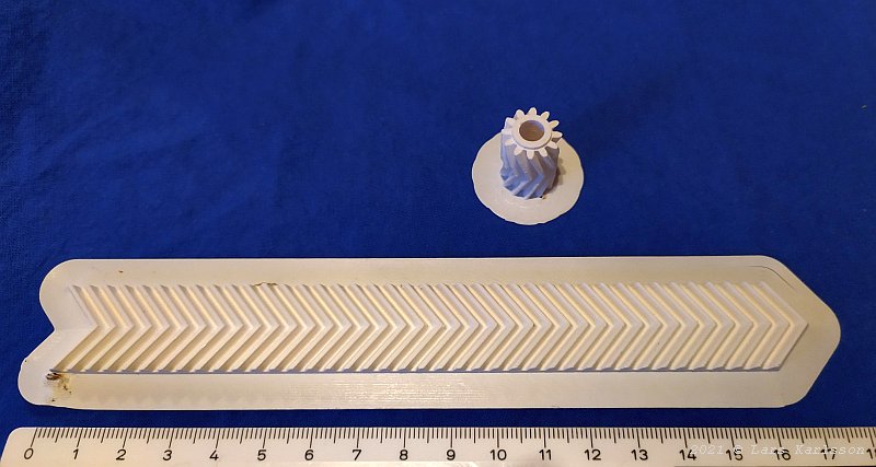
With a matching rack, about 150 mm long. 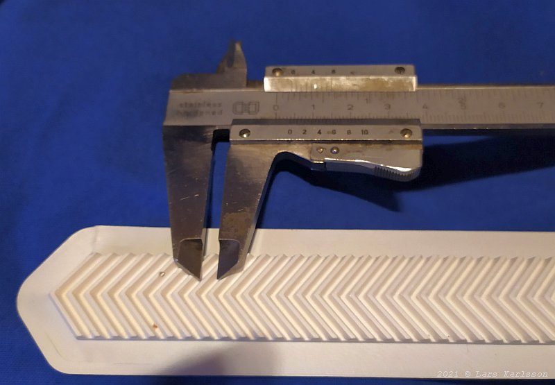
The distance between two teeth is 4 mm, that is the pitch. 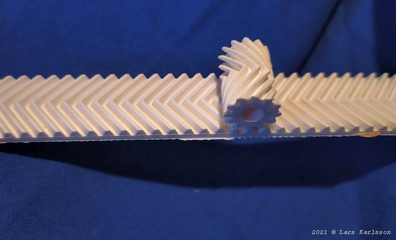
Something is wrong here, the pitch of the teeth doesn't match each other. Have to read more about making these kind of gears. It looks very promising, never any more slipping problem if I get it to work. As usual when you try to do something special a lot of new problems appear. Why doesn't the rack and pinion gears match each other ? Is it I who do something wrong or is it the calculation in the Gear module that's wrong ? I measure the gears size and calculating backwards what module they have. To my help I have this document:
The equation to calculate the module of the spur gear look like this with my figures: Spur gear (14 mm outside diameter and 12 teeth) Module = 14 / (12 + 2) = 1.0 mm That is correct. Rack (length = 159.5 mm and 40 teeth) 40 teeth means that it is 39 pitches between them. Gives a pitch distance of 4,0897435 mm. Module = (159.5 / 39) / PI = 1.3018 mm The module is wrong for the rack, it was set to 1.0 mm in the FreeCAD. Module 1.0 is a bit coarse, how does the 3D-Printer handle module 0.5 mm ? Let us try that setting. 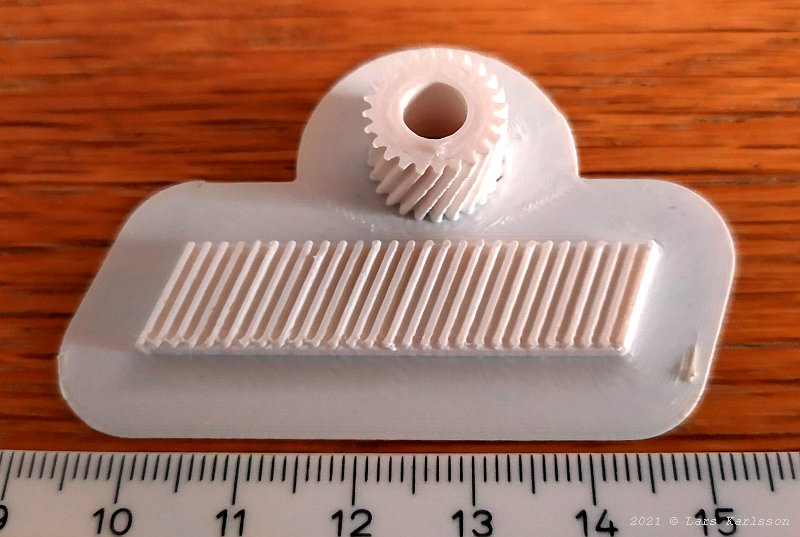
In this case I only CAD a single helical to get it faster. It looks to my surprise relative good. To get the teeth match each other I set the module of the rack to 0.47 mm. I found this value by visual inspection in the FreeCAD. If I calculate backward the module of this rack I printed I get it to 0.49515 mm, very close to 0.5 mm which I aimed to. 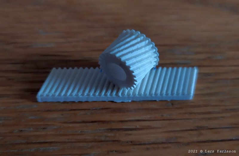
The teeth match each other, but got the helical mirrored. The question is: is it better to use the module 0.5 mm or the module 1.0 mm ? But first I must find out why I get the module size of the rack wrong.
Update: 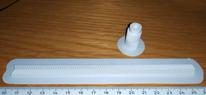
With the experience from above test I designed a new prototype rack & pinion gear, now with module 0.5 mm, double helical with 20 degrees angle. When I moved to module 0.5 mm I got a much lower design which make it easier to implement in the old 3" focuser. Very limited space there. 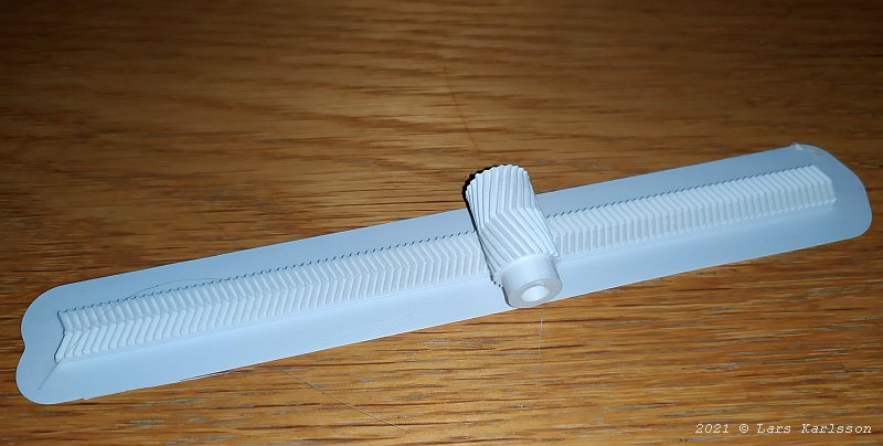
Now the teeth match each other very well. But you must have in mind that the fine adjustment of the focuser is in a few my range. The external gear box between this rack & pinion gear and the stepper motor must have a higher ratio too. Maybe something around 1:65, I will do a calculation about it later when I have decided what diameter the spur gear will be of. What kind of filament you use can have big impact on the quality of the gears. Here I have found a site that test different kind of filament:
|
|