|
Advertisement / Annons: |
My astronomy project:
|
Content:Implement of external push pull screws:
Related projects:
Note: |
2: Stabilization of the focuser draw tubeWhen the push pull screws push the focus drawer tube back and forth it's very important that the focuser draw tube only do it in a linear transfer along the optical axis, no wobble. Earlier this was done by the friction focuser shaft that pressed down the focuser drawer tube against four roller bearings. Now when it's gone I must replace it with something else. 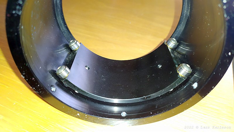
In the bottom of the focuser drawer tube it takes support against these four roller bearings, it's the original. 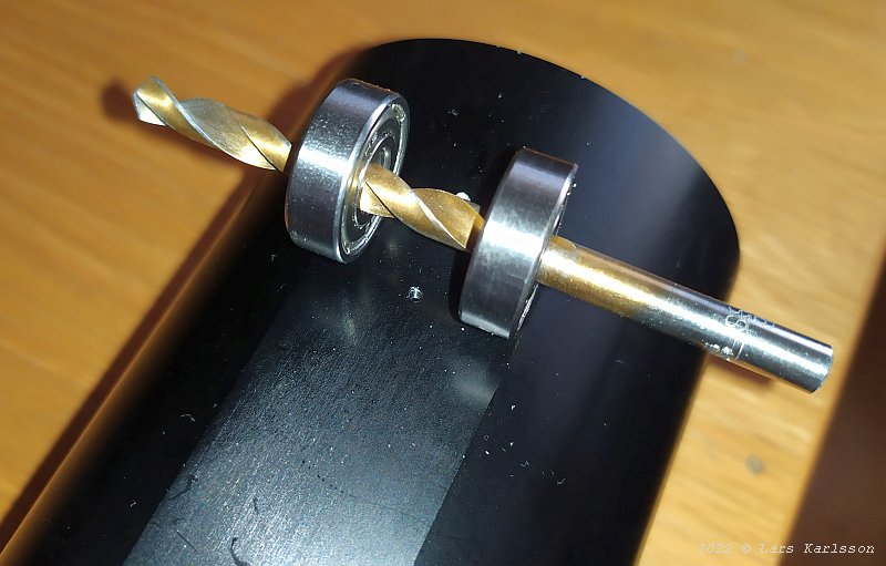
At the upper side it has to be pressed against the bottom roller bearings. I plan to use two roller bearings to get lower friction compare to the earlier friction shaft. An illustration how it's supposed to work, the black part is the focuser draw tube with its flat surface. They are placed sideways to stop the focuser draw tube from rotating. Design with single upper puller screw: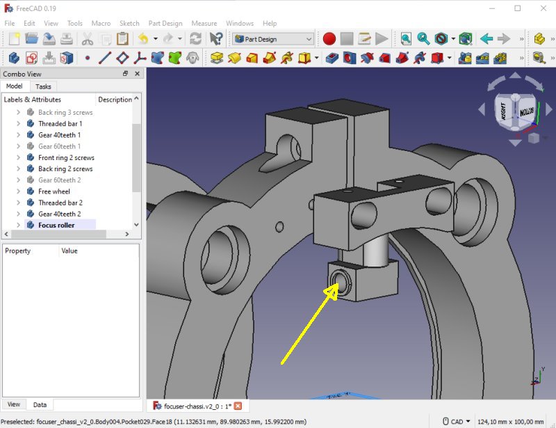
This is the device that keep the focuser draw tube to be pressed down. Where the arrow point it will be a 6 mm stainless steel shaft inserted. On each side there will be a 6x12x4 roller bearing. The force is applied between the two roller bearings. I skipped this solution and went for a more advanced solution. Design with two puller screws: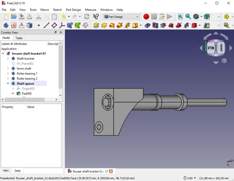
I have an alternative solution to it. A longer shaft that protrude outside the chassi in a similar way the friction shaft did. The force in this case will be applied at the two ends. It will give more stability sideways, but the space is limited so maybe not possible. I think this will be a much better construction but more complicated. One of the problems is to find the correct places for the holes and there is a mix of inch and mm. 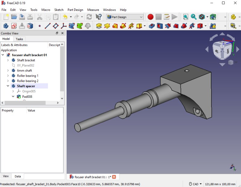
It will be another shaft bracket on the other end too, it's a mirror of the first one. What force is needed ? A rough estimation: If calculated for a camera system of 5 kg, its center is about 160 mm from the first roller bearing. The force is applied 20 mm on the opposite side of the roller bearing. It's a 8:1 relation, 5x8 = 40 kg or 350 Newton. If it's divided by to places, 175 Newton each, it can be handled by two M4 screws. Maybe I have to reinforce the plastic. First 3D-print: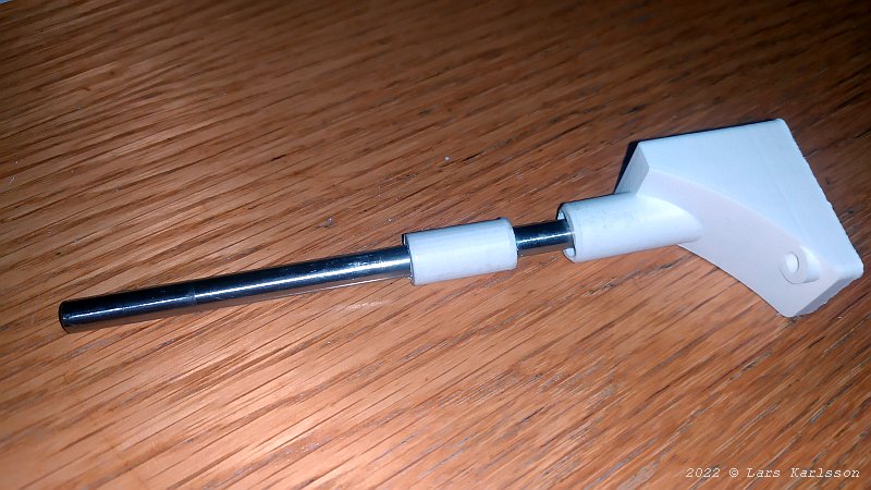
At last I can 3D-print my prototype, I have repaired my printer and it prints with higher quality now, much smother surfaces. The 6 mm shaft with the roller bearing spacer and the shaft bracket to the right. 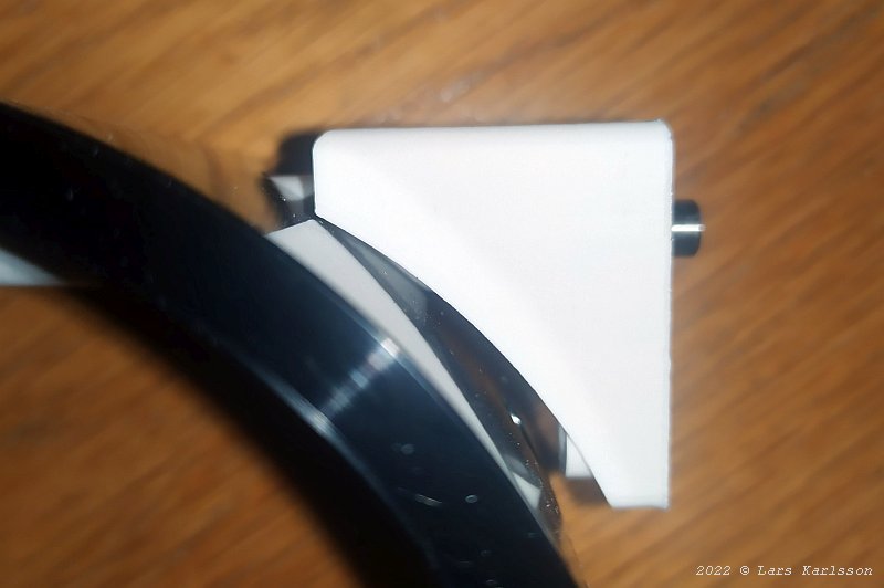
The part that goes in the focus bracket fit perfect, but I got the hole in wrong height. I'm not surprise because it was very difficult to find the distance with these curved shapes and the mix of inch and mm. 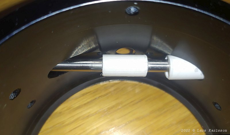
Inside where the focus drawer tube is placed, the spacer that separate the two roller bearings. Installing focuser draw tube's roller bearings: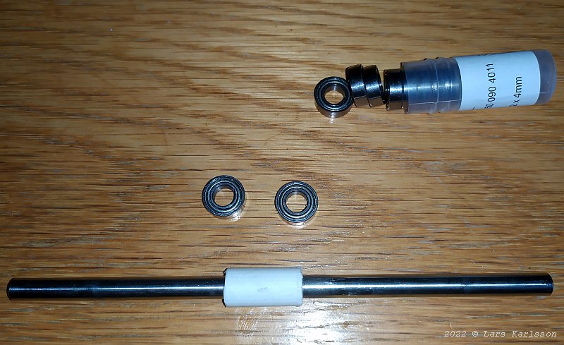
Today I got the special roller bearings I ordered, they are of a thin model, 6x12x4 mm. I ordered ten of them so I have for future projects too. The outer diameter can't exceed 12 mm if they shall fit inside the focuser chassi. 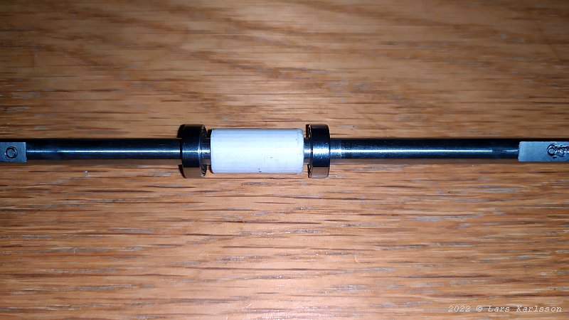
The 20 mm wide plastic spacer separate the roller bearings. 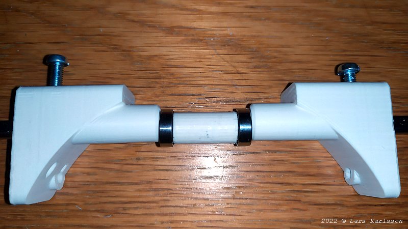
The left and right shaft brackets center the roller bearings. 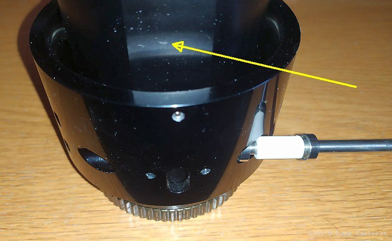
The shaft and the roller bearings must be inserted from aside when the focus drawer is in place. The flat surface is where the roller bearings press against, it must point in this direction. 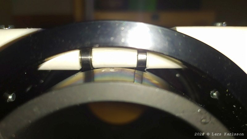
A look inside and you see the roller bearings are against the flat surface of the focuser draw tube. It hold the focuser draw tube in place without any play, it also block it from rotating. 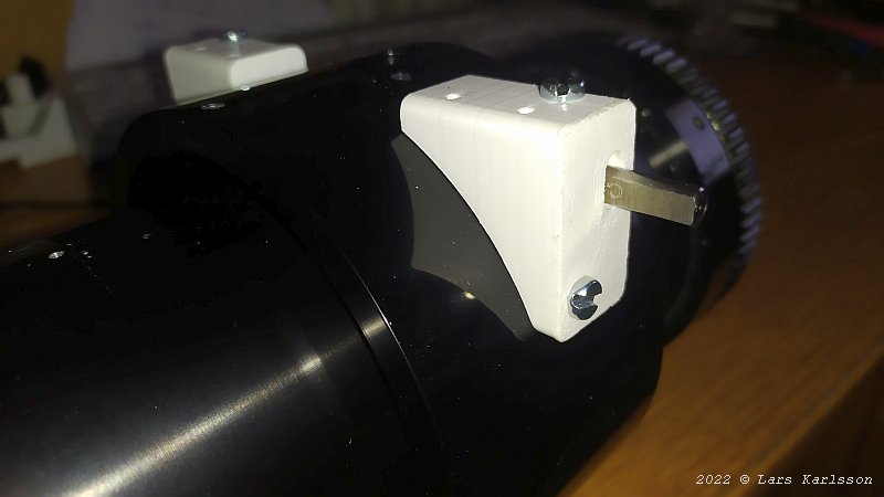
The top screw set the force that the roller bearing press at the focuser draw tube. What I feel the plastic will be strong enough for this. This worked as a charm, much better than I could have dreamed off. Drawback of soft aluminum:But of course everthing could always be a little bit better. 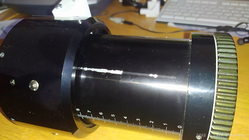
Where the original roller bearing has run against the focuser draw tube it can be seen marks. The aluminum is too soft to be a perfect solution. More advanced focuser use linear steel bearings. If this surface had been grind flat I could have installed that too. I will try to polish this surface to have it more smother. 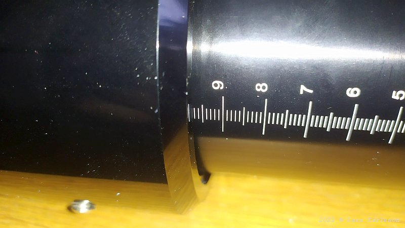
The stroke of the focuser is now 97 mm. Later when I have installed the push pull M3 rods it will be reduced, maybe to 60 mm. It doesn't matter, you should never use the focuser near the full out range, it's not stable enough for heavy loads at that position. 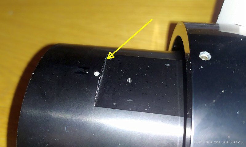
The roller bearing hit this edge, that's why the stroke is reduced from 100 mm to 97 mm.
|
|