|
Advertisement / Annons: |
My astronomy project:
|
Content:Implement of external push pull screws:
Related projects:
Note: |
3: Assembling the Push Pull systemNext thing I have done is to adjust the design of the front ring clamp that holds the two M3 push pull screw rods. I go for M3 instead of M4 to increase the resolution. With M3 screw rods I get 2.5 my per full step when the timing belt gear is 1:1. One more important thing is that the thinner M3 screw rods give less unwanted force on the focuser draw tube bearings. M3 screws are more flexible compare to M4 screws and reduce the risk of any side forces. Front ring clamp: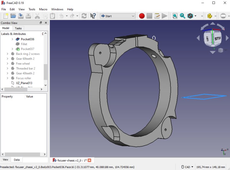
When I redesigned the front clamp I also tried to reduce the size of it, I did it tighter and reduced the diameter of it. It was difficult to take account for every little detail. One important thing, the timing belt is not allowed to hit anything when it moves around its path. 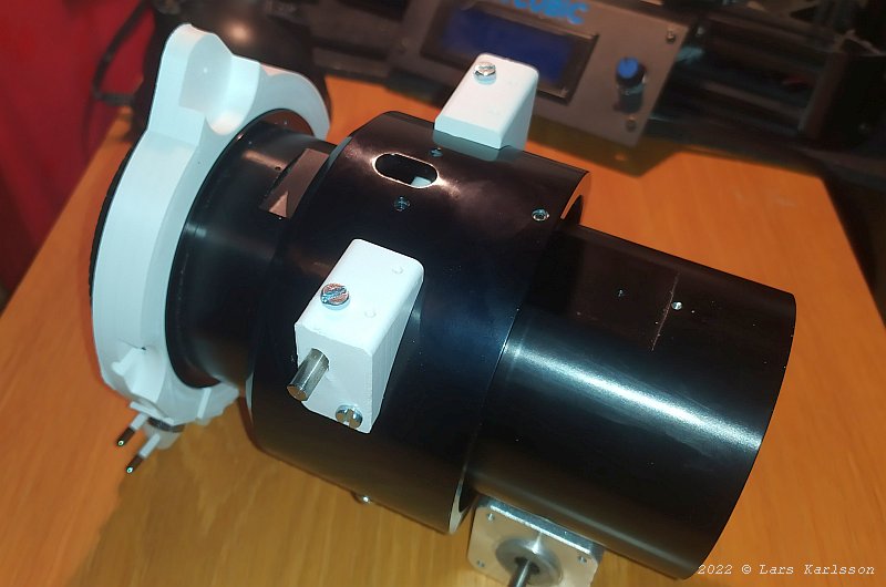
I see now that I reduced the diameter of the front ring clamp too much, but can still use it as a prototype. Otherwise most details are okay. I have to rotate the clamp to get the stepper motor in a good position, not protrude too much on the sides. The stepper motor is heavy and balance the guide telescope on the other side to some degree. The M3 screw rods must clear the two brackets, if necessary I can make a hole in them where the M3 screw rod can go through. Back ring clamp: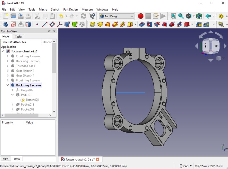
The back clamp, even for this I have changed the design to reduce its size. Still the stepper motor protrude far aside, if I skip the adjustment of it it will be more compact. But then I have to add a free wheel that can set tension on the timing belt. Maybe I at the end will find that a NEMA 17 stepper motor is an overkill and I can use a smaller NEMA 14. It's relative easy to 3D-print a new bracket for it. 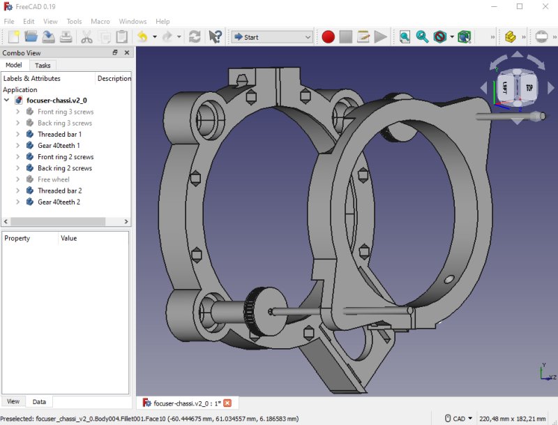
All parts together. I have also added more holes for future equipment, they are made for M4 screws. One of the extra items is a box for the driver of the focus motor. 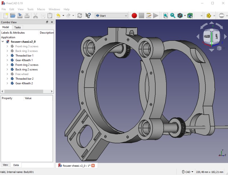
I will let the holes for the roller bearings on one side of the back ring clamp be two mm deeper, then I get more space for the locking nut. Next step is to finish the design of the free running wheel and the timing belt gears. I must design a M12 thread at the end of the shaft to have it fixed against the roller bearings. That's something I have to learn how to do. 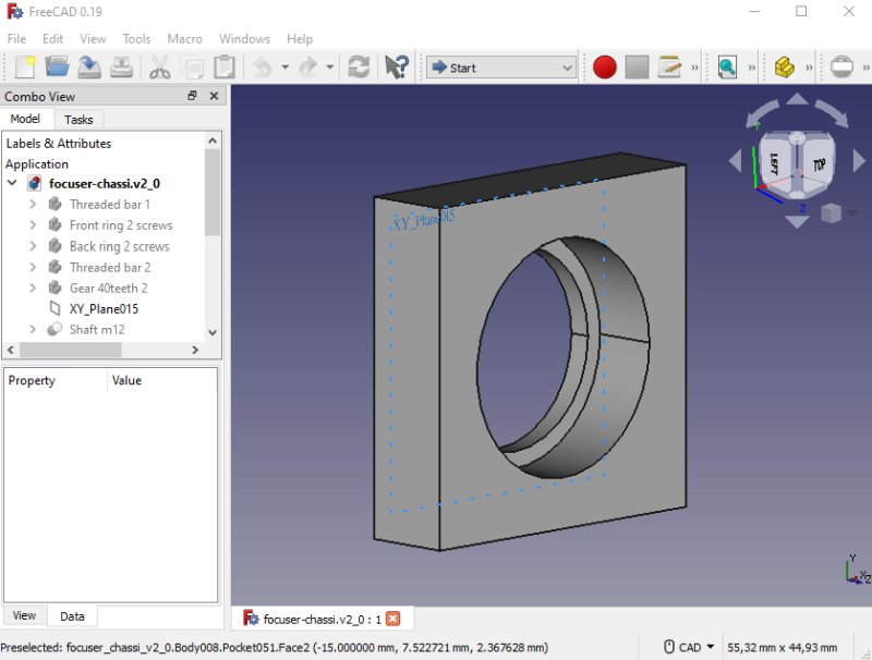
The back ring clamp is a 10 hours 3D-print project, I must check everything I can so no mistake is done. One thing is the holes that hold the 21 mm roller bearings, do they fit direct or do I have to oversize the holes ? To investigate that I have designed this test jig, it's a 21.0 mm hole. 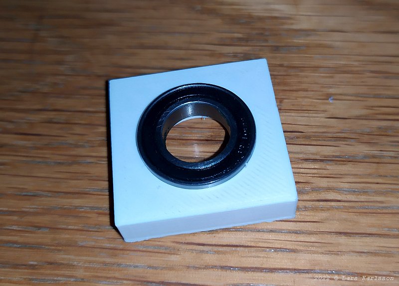
It fits perfect, it's amazing, how can the precision be so high ? Free running wheel: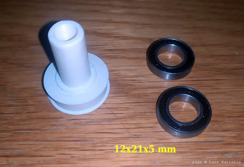
The free running wheel and its hollow shaft. This free running wheel will only support the timing belt to get free from the chassi. 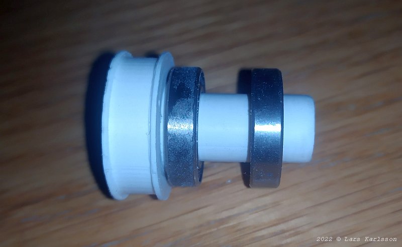
With the two roller bearings mounted. My plan was to thread the shaft at the end and lock it to the rolling bearings with a nut. The shaft protrude 5 mm behind the roller bearing, but I must short it to three mm, otherwise it will hit a bracket. 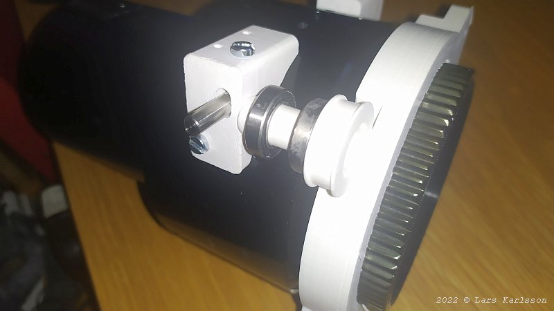
The focus draw tube at full in position, the zero focus position. The pockets in the front ring clamp let the focus draw tube go all the way in. 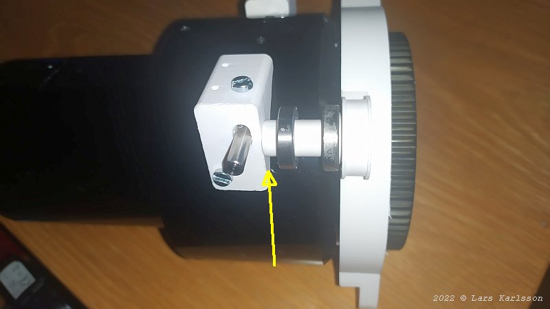
The shaft come too close to the bracket. I have to shorten it 3 mm to let it go free. Three mm will be left and that's very short to have M12 threads on, the shaft has a diameter of 12 mm. Maybe I can do it as simple as only put a drop of glue on the shaft to lock it to the roller bearing. There is no big force here but there is some play in the roller bearings that must be handled, then the idea with glue will not work. Timing belt gear: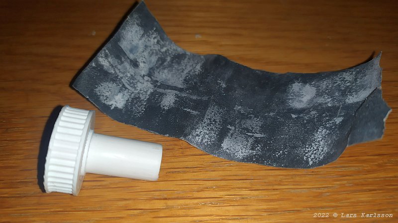
This gear has 40 teeth which I think will be enough, it's the GT2 standard and 6 mm wide. The surface of the shaft has to be smother and I use a 400 grid sand paper to do that. 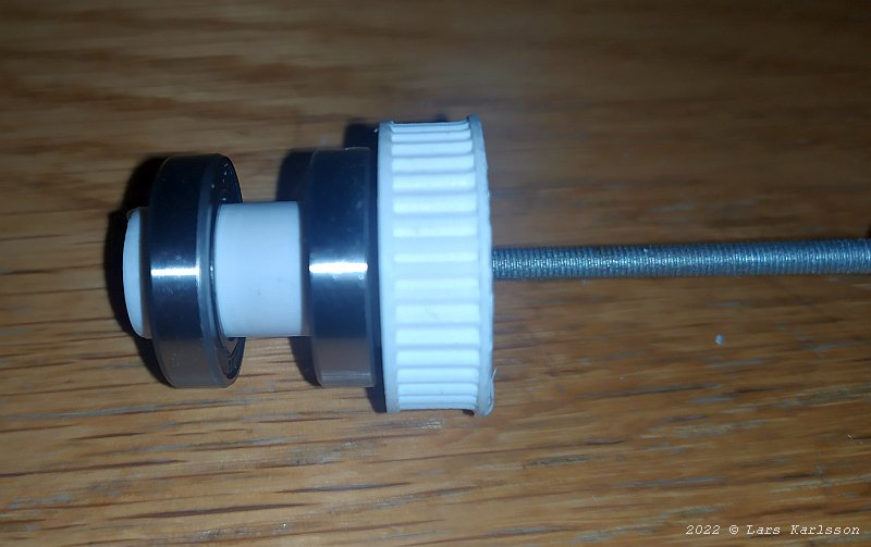
I start it simple, drill and thread the shaft for M3 direct in the plastic. I'm not sure for how long these threads will last. Maybe I have to do some more advanced solution later. It could be some spring loaded M3 nut made in brass. I can feel some play in the roller bearings, that's normal, I think I have to set them under some force to eliminate the play. 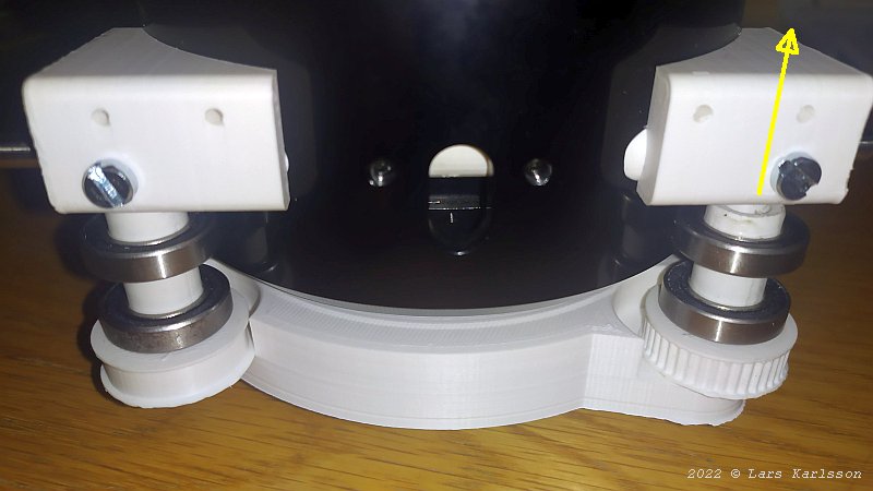
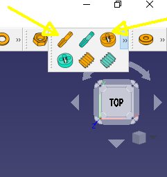
When focus is at full in position the M3 screw rod must go through the bracket. I have to make a hole for it, very narrow space here, as usually when coming to the details. There are twelve roller bearings now in this focuser. Threads:I need to have threads on the shafts and a matching nut to it. To get this to work the threads must be with fine threads, i.e. M12x1.0. I found that the FreeCAD's Fasteners tool can do this, FreeCAD already have this tool but you must install it first. It's done from the menu: Tools>Addon manager>Fasteners. Then restart the program. More information about Fasteners:
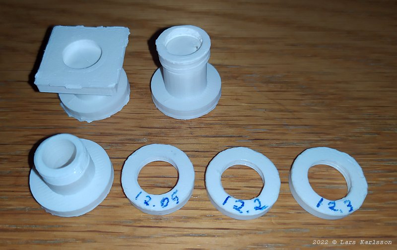
Above I have my different test of 3D-prints of threads. The nut must be a bit oversized to not stick too hard on the shaft. I tested different sizes: 12.05, 12.2 and last 12.3 mm. It depends very much on the 3D-printer how much you need to oversize the nuts, in my case the 12.3 mm diameter fitted best. With this experience I can now make the real threads on the Free running wheel's shaft and the timing belt gears' shaft. 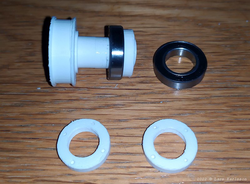
The 3D-printer have a hard working day today. I added four small holes on the nuts so I can use a tool when tightening them. The free wheel top left with one of the two roller bearings installed. 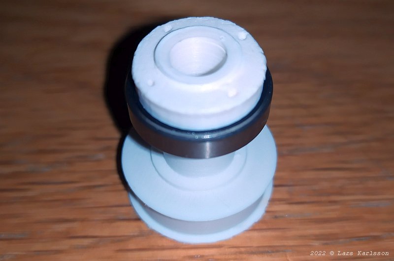
It's amazing what you can do with a 3D-printer today. Who had believed a person who told you that you can 3D-print gears and threads 10 years ago ? 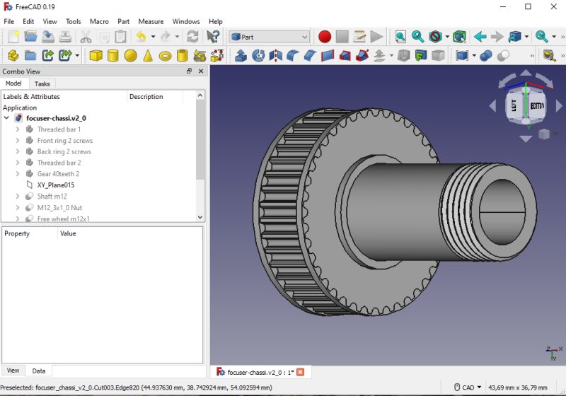
Threads on the timing belt gear. It's the same size and construction as the free rolling wheel. 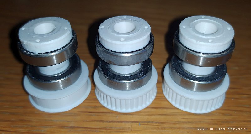
The free wheel and two gears finished.
|
|