|
Advertisement / Annons: |
My astronomy project:
|
Content:
Note: |
2: Making brackets for motor focusI have now come to the part where mechanics must be designed / adapted between the telescope and the motor focus. 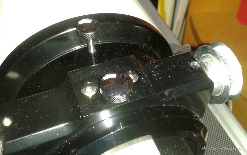
Apparently there are not many holes at the telescope that can be used. I want to get this to work without drilling new holes in the telescope. I begin to plan to use the big locking screw for focus and the set screw for the holder block. It is the big screw at front and the countersunk Allen screw to the right. It was lucky that it's M5 thread, otherwise it are a mix between US Inch and Metric standard. 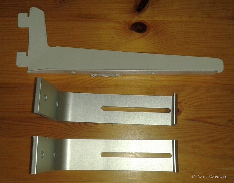
I looked for aluminum profiles in my boxes but found none exactly as I wanted. Took a tour to various warehouses elsewhere, at a flea market I found a scrap box of assorted profiles. Bought me 4 parts of those, above shows the three which did not get in use this time. 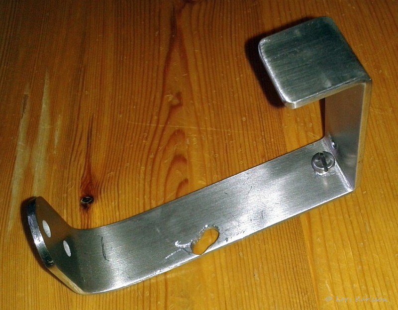
Here is the profile that I began working with, it's a curtain rod to be attached to the motor focuser. It is made of stainless steel, that material is not so easy to drill, you need a drill of high quality. Have curled up on one end which can be attached to the stepper motor connector. Also drilled hole for the motor and fastening screws to the telescope. 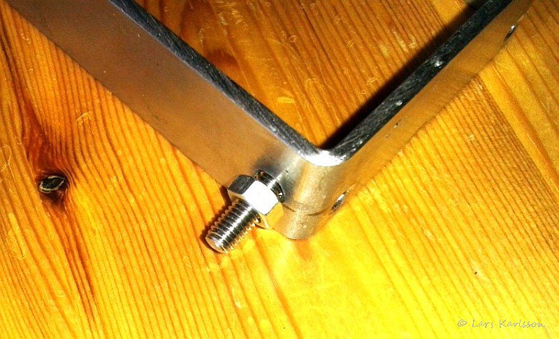
The outer fixing screw against the stand may also be a device to tension the timing belt with. It is done by a nut that is tightened against the profile and then washers to fill up to the profile and lift it. 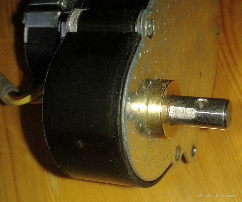
The axis from gearbox has been flattened so that the pulley's lock screw will lock properly. 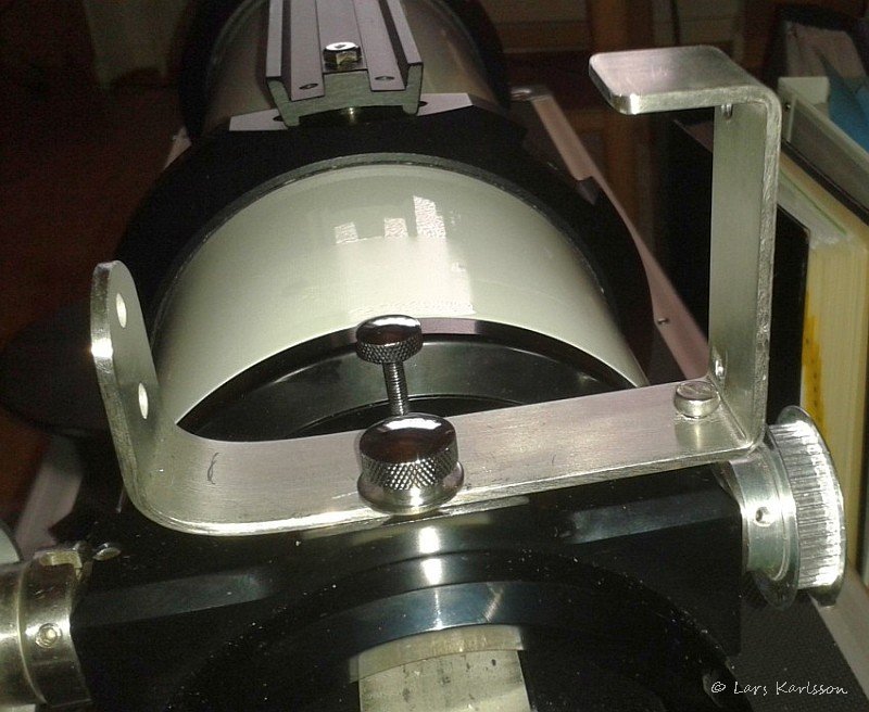
A first sample mounting bracket to ensure that no surprises emerged. 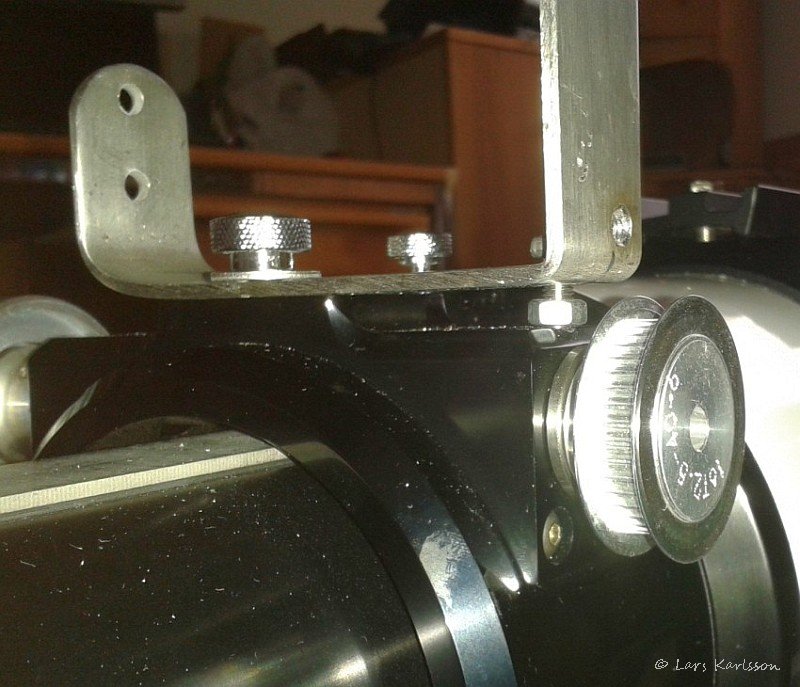
Here is the bracket from below and the nut which was mentioned earlier and which shall serve as straining for the timing belt. (Update, I will replace the nut with a distance so I can tight the profile harder to the the telescope and then reduce some flexure that I have noticed when I used it later) 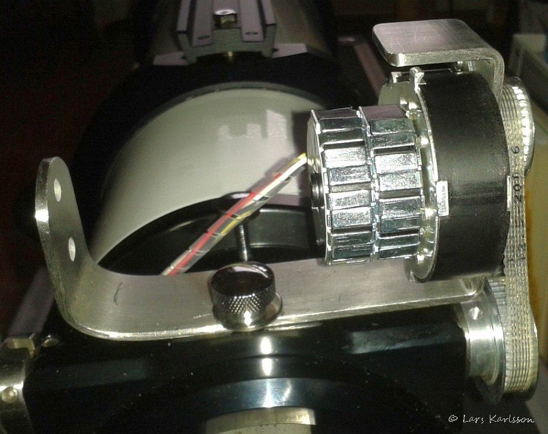
The stepper motor is mounted and the timing belt to be tested so that it is sufficiently tight and that the pulleys are rotating as they should. 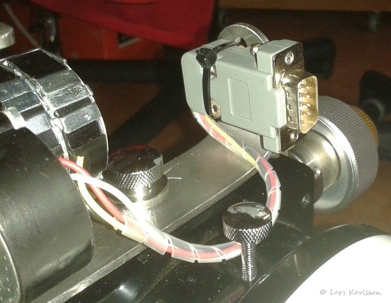
The electric connector mounted on the bracket's outer edge. Feels good that it is mechanically locked to prevent the wires to the stepper motor to rip off. 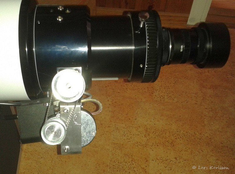
Stepper motor assembly seen from the pulleys side. 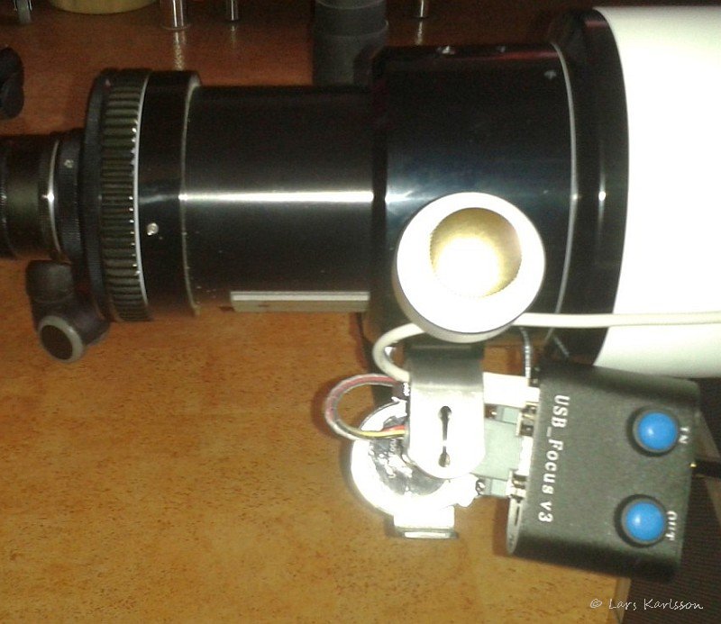
Focus motor seen from the stepper motor side and the control box attached. The DB9 connector has lock screws so that it doesn't jump out, they give a warning in the manual of the stepper motor because the inductive discharge may arise if the cable comes off and thus destroy the electronics. The pulleys has a gear ratio of 3:4 which allows the digital scale to be better utilized. The focuser has a free run length of 100 mm and it goes from 0 to 56,500 step, max on the scale is 65,500 so the range is used well. An alternative solution would have been with a shaft coupling. But it gives clumsy montage, and you miss the opportunity to have a ratio between focuser and focus motor. Also notes that it is mechanically manually possible to focus, it draws around the gearbox and stepper motor, but is not recommended as dangerous voltage spikes can occur that destroy the electronics. It also drops sync between focus motor and the digital scale. This really is something that I wanted for long time that now will be exciting to try it in practice. I have some problem with the software but suppose it will be solved with time. In early test the stepper motor stalled, but that was due to the timing belt was unnecessarily hard tightened. One can imagine that there will be problems when connecting a heavier camera, but then you can connect the control electronics to an external supply of 8 volts and thus get more torque on the motor. (Update, today I run the stepper motor at 8 volt externally, huge difference)
|
|