|
Advertisement / Annons: |
3D CAD drawing:
|
Contents:
Note: |
3, Design bracket version 2.0:Rearrange bracket and the USB-Hub holder:I connected the USB cables and testing with different different position of the bracket. I found the optimal design if I move up the USB-Hub and tilted it 90 degrees. With this the bracket can be moved one hole to the left and I get more space for my guest camera on the right side. I must have something interesting for my friends if they follow me out in the cold night. Sketch of new design, version 2.0: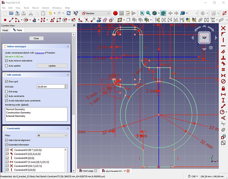
This was the design I came up with, lower the foot 3 mm, raised the USB Holder about 35 mm and moved it to the right. There will a second bracket, or tube ring also. This will fit the Tokina 200 mm lens that I use. The design will be almost like this one, only the rectangular box removed and a smaller inner diameter hole. Making nut pockets: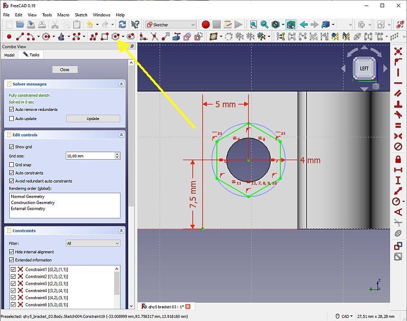
One thing I wanted to add was nut pockets, hexagon holes that the nut can be pressed into. It was much easier than I thought. Do as with a normal hole but use the multi polygon tool in Sketcher. If you want the hexagon in some special direction you can mark one of the line and set it parallel to some axis. 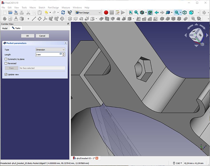
It's fantastic, if had to do this in a metal bracket it had been very complicated. But in that case it's solved in another way because of the problem to do it. 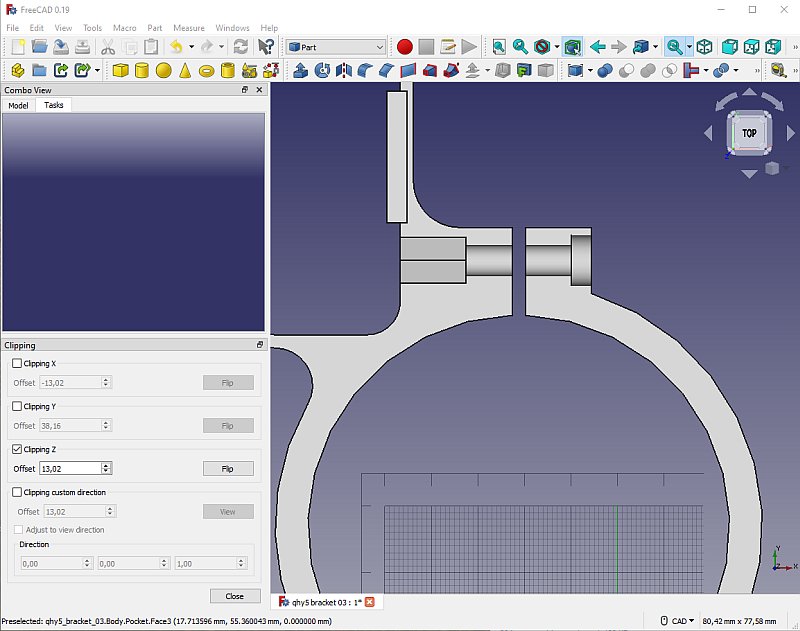
After some thought, I think it is better to make the hexagon pocket deeper. Otherwise you must have a very exact length of the screw, it can't protrude outside on left side, that space is already occupied by the USB-Hub. I open the Clipping tool, it can be open when you adjust how deep the pocket shall go. Very practical. A control if it's printable: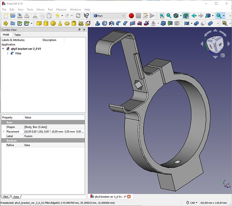
Before I proceed to far with the drawing I Export the drawing as a TSL file and open it in Cura. All holes were there. Back to FreeCAD and add some round corners. Add a more complicated nut pocket: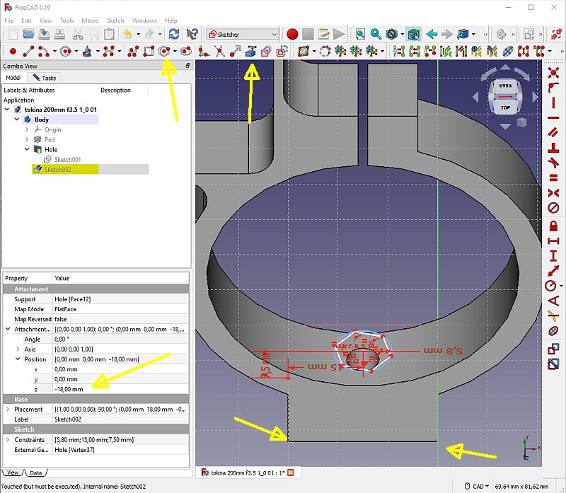
After some thought, I must have a nut pocket to the bottom screw also, a M6. I didn't do it first because it looked so complicated, the surface is not flat and then the Part Design tools doesn't work. After some research on internet I found a way to do it. Do a normal Sketch with the bottom plane that is flat. Then moved it up above the curved surface. After that, proceed as normal. 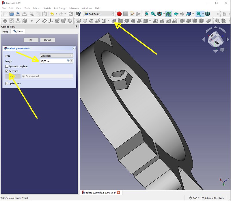
I had to reverse the direction of the pocket. I go stepwise all the way down to the bottom, then back of 8 mm to have enough material to keep the strength. I used the Clipping tool when I did this. After I had printed out this bracket I found the the hexagon hole could be a bit wider. I added 0.2 mm to the diameter, this is a little bit printer dependent. |
|
|