|
Advertisement / Annons: |
3D CAD drawing:
|
Contents:
Note: |
1, EQ6 Pad design:Introduction:When I put the EQ6 head on my pier I must have a pad between. I made one of wood to test and the plan was to replace it with one made of aluminum. But now when I have my 3D-printer, can I 3D-print a pad or will it be too weak to work properly ? Of course I must do a test. The old pad or distance: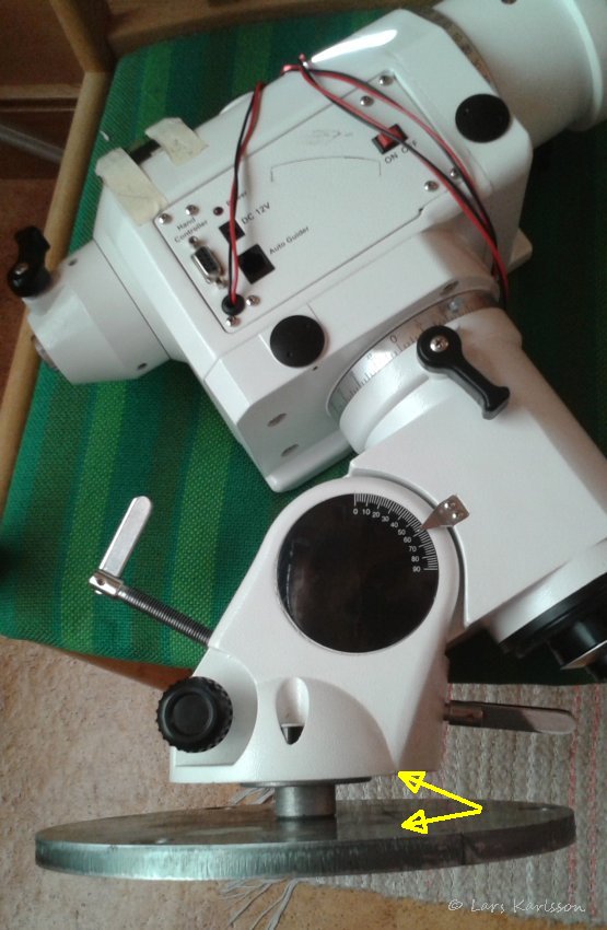
The EQ6 mount head isn't flat at the bottom. To attach it to the pier I must have some sort of pad between. The disc at bottom is a part of the pier. The pad is also needed to raise the mount above the disc, in combination with my camera lenses I can have an extender of 300 mm instead. If I do a new disc in the future I will use a disc brake from a car which has a higher central part. Then I can have a bigger hole but need a very big washer on the bolt side. An alternative as someone suggested is to make a bigger hole in the disc. But then only the Q6 mount will fit and it's not so easy to make a 65 mm hole in the steel disc. Metal oxide and rust, plastic not, that is one more advantage to use this 3D-printed pad. The material cost to print it is about 4 Euro, if I had let a workshop made in metal it had cost at least 40 Euro for a simpler version of it. Dimensions of mount's foot: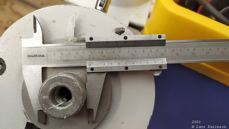
The center tap has a diameter of 29.3 mm, in the CAD drawing I have to set it a bit larger to compensate for the plastic material. 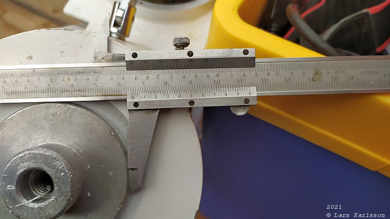
The middle extension has a diameter of 64.9 mm. 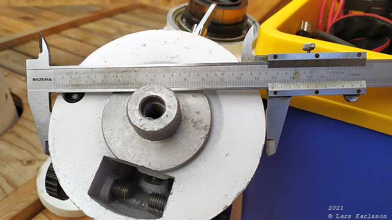
The overall diameter is 129.3 mm. Wooden pad: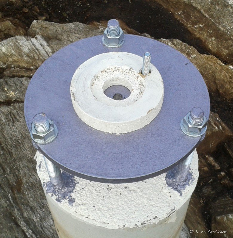
I made my first pad of wood to check if I got the correct distance between the EQ6 mount and the pier. My original plan was to replace it with one made of aluminum. If I install my HEQ5 mount on the pier I need another pad of different size. The disc is designed to accept an EQ8 mount, the big diameter cause some problem when using a smaller mount. When having higher load I muster lower down the disc, otherwise the long bolts (M18) can cause some flex. CAD of Pad: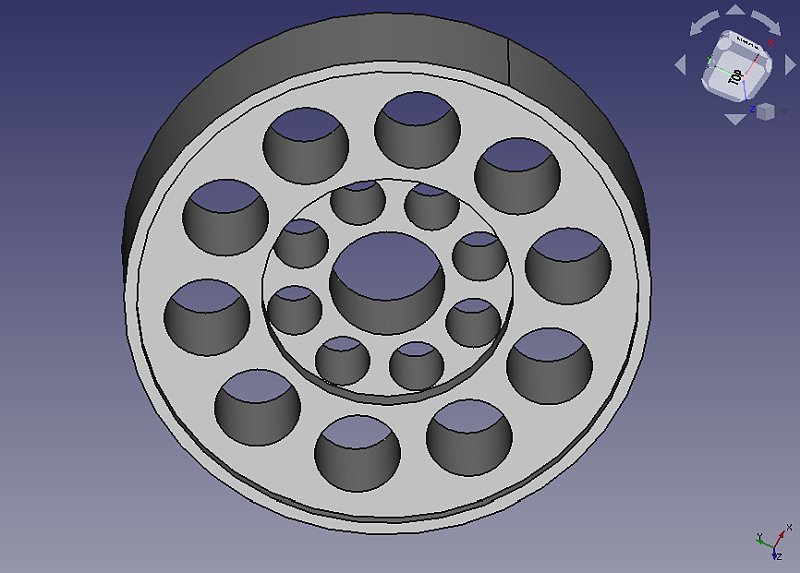
Is the plastic material stiff enough to work as a pad for this purpose ? I made a CAD and let the 3D-printer print it. 12 Hours work and 200 gram of material, still waiting for it to be finished. Set the bottom, top and walls to 4 mm, 30% fill factor. I made a lot of holes to reduce the material consumption and still have it stiff enough. In one of the outer holes the azimuthal adjuster will sit. When I started printing I noticed that I didn't bought PLA filament which I had before, this new filament is ABS pro. I had some problem to get it stuck to the printer bed. I increased the temperature from 200 to 230 C degrees, and the print nozzle from 60 to 80 C degrees. I will come back later when it's finished and mounted with a report. If it work as I hope I put the STL file here for download. My project: Pier page. |
|
|