|
Advertisement / Annons: |
My astronomy project:
|
Contents:
Note: |
2, AstroEQ, does it fit ?AstroEQ: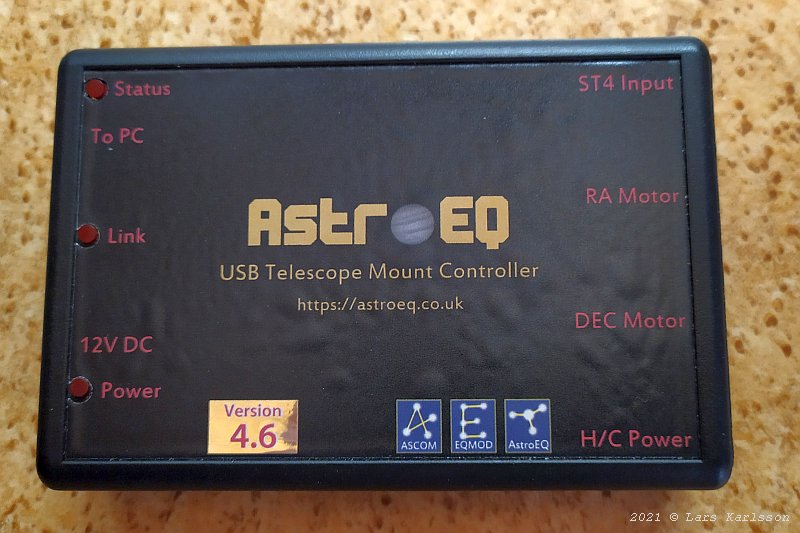
This is how the AstroEQ driver looks like. It has an USB port to connect to the PC/Raspberry, no need for a EQDirect cable. That's very good and it operate from 12 volt. 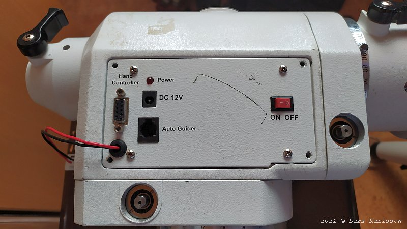
The original driver board sits inside the EQ6 mount's chassi. 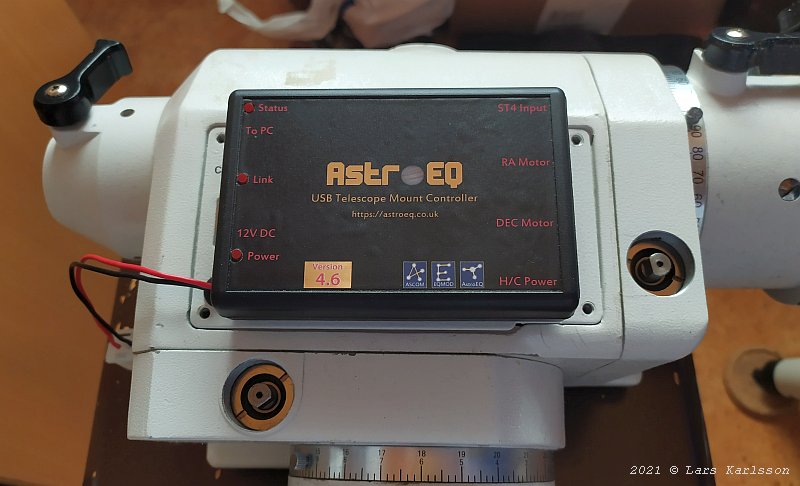
I can easily place the AstroEQ box on top of the EQ6 lid. 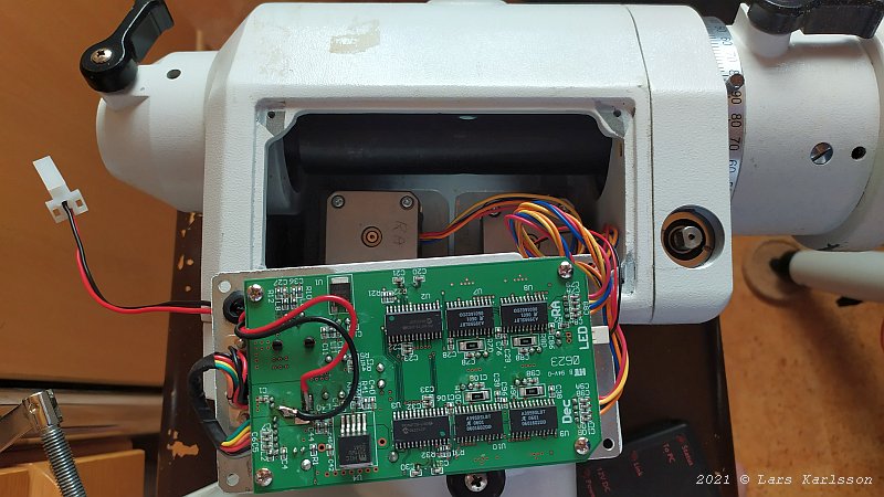
Or, could it be placed inside ? This is the original circuit board. 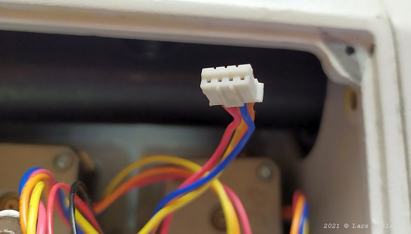
The stepper motor has these connectors, they are called JST and these has 2.0 mm pitch. The AstroEQ use RJ11 6/4 connectors to the stepper motors. I don't want to cut the wires and need to make adapter cables between. 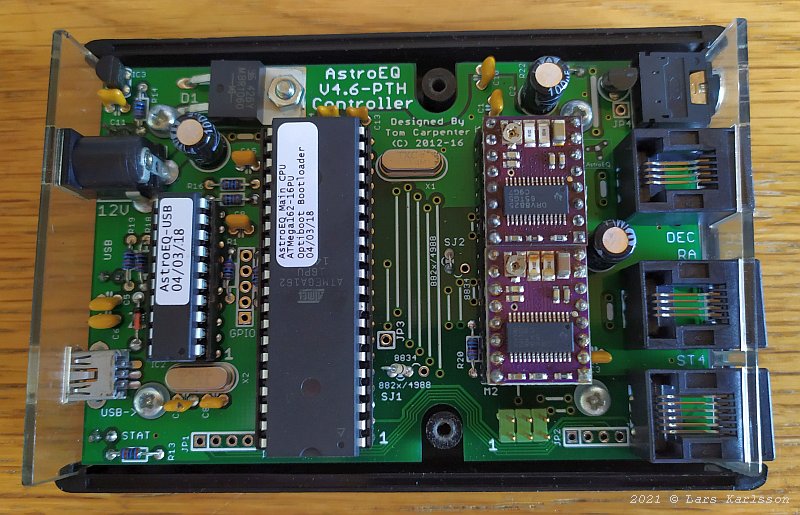
The electronics inside the AstroEQ, the red circuit board is the power driver to the stepper motors. There is a potentiometer where the max current can be set. Much more flexible compare to the original driver, more stepper motors to chose from. On the left side: USB connector and Power inlet, on the right side: ST4 port, RA and DEC motors and a hand terminal power outlet (I think). 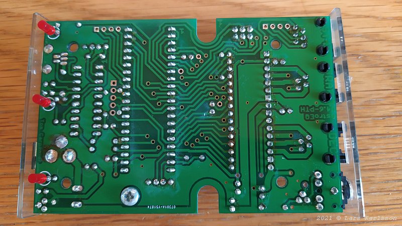
On the other side, the three red LED indicators: Status, Link and Power. 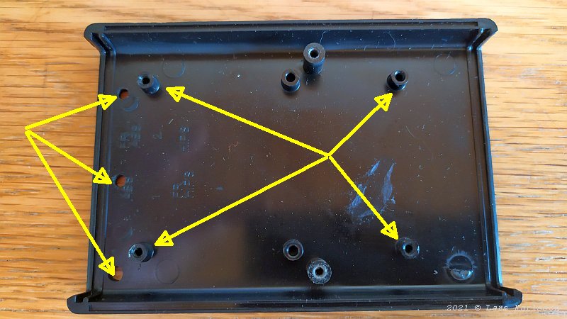
The box has three holes for the LED and four towers that hold the circuit board. If I 3D print a totally new enclosure I must get these holes and towers in correct place. 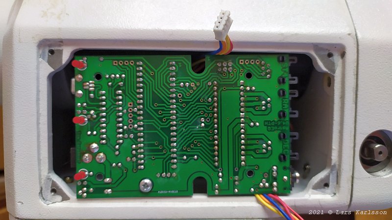
Just checking if there are space enough to hold the AstroEQ circuit board inside the EQ6 mount. It's the cables that cause problem. 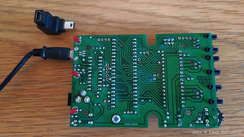
It will be a very sharp bent on the USB cable, I have a 90 degree adapter, but too big and in wrong direction. 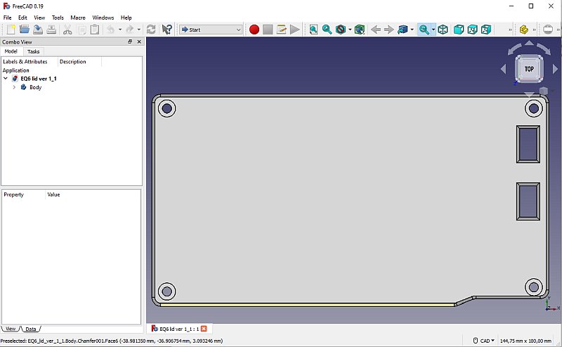
I start with 3D printed flat panel that replace the original EQ6 lid, with a double sided tape I place the AstroEQ box on top of this lid. This 3d printing project is on this page, EQ6 lid.
Update:
|
|