|
Advertisement / Annons: |
3D CAD drawing:
|
Contents:
Note: |
4, Design of the lid and 3D-print:Info:I need a lid to my Power terminal, the plan i that the Volt and Ampere meter will sit on this together with the main switch. The lid: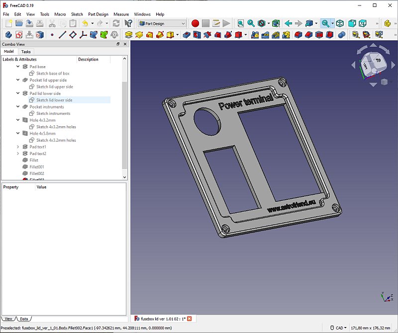
After a couple of hours I have the lid drawing finished. It's built in two levels to get it stronger, looks better too. 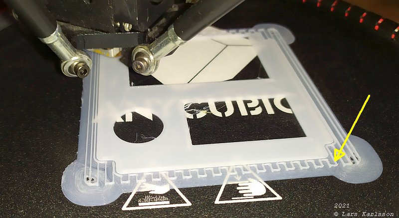
When 3D-printing details that have an overhang it must be added support during the printing process, it can't print in the air. This is how the slicer designed the support. It's printed as a thin framework below the edge that need this support. 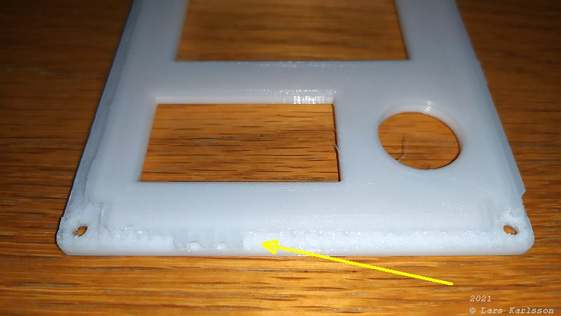
First thing to do is to get rid of the support plastic. I used a sharp knife, be very careful, the plastic is hard and you don't want blood all over the place. Grounded the last down with a file. 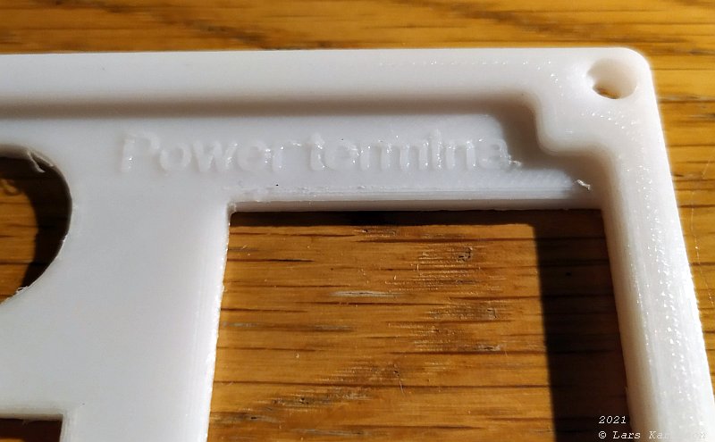
The 5 mm text is clearly seen. 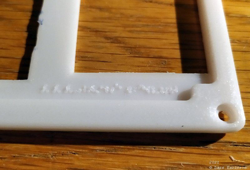
The 3.5 mm text can't be read at all. 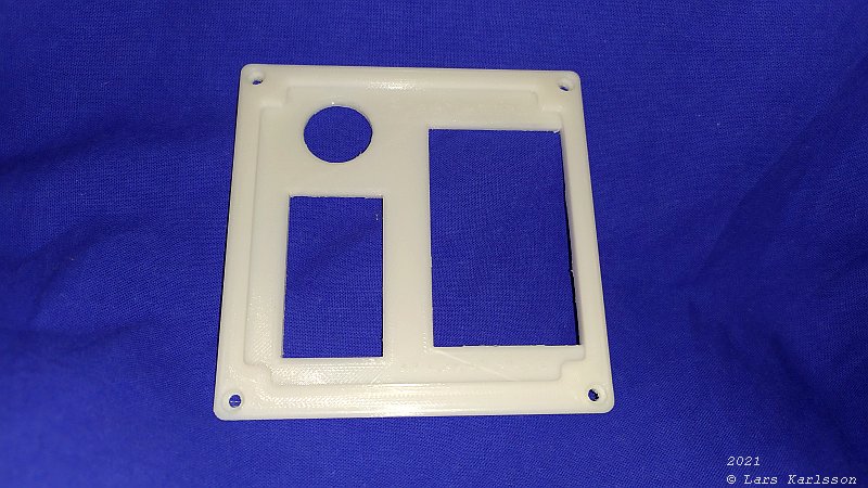
Time to install the Volt and Ampere meter. 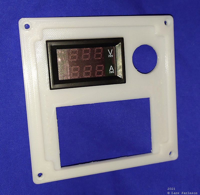
It was impossible to push it all the way down. 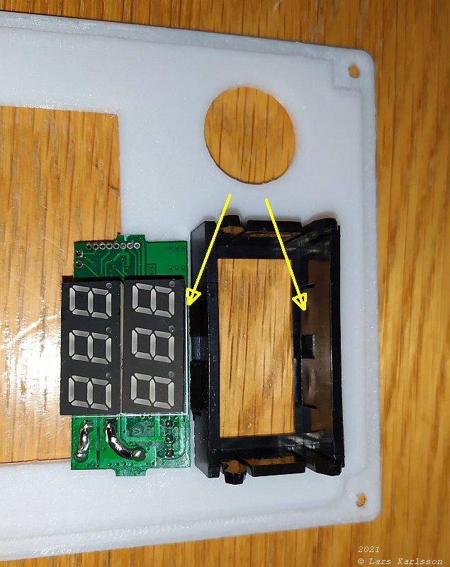
Wrong in the construction I believe. The four spring loaded hooks collide with the display. 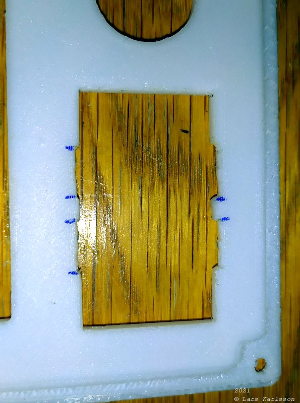
File out four extended edges. But there is a problem, the frame of the instrument have the same size now as the opening. 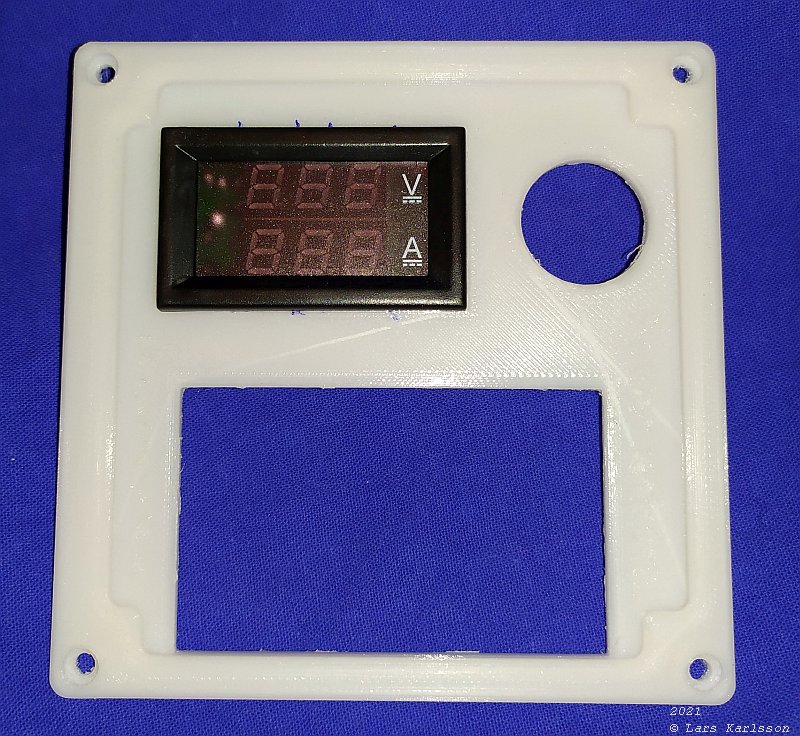
In place, but it don't fit very well anymore. 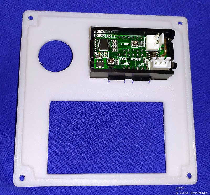
A look at the backside, I shall widen the opening in the drawing. 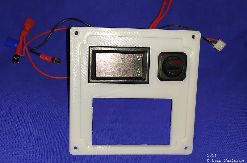
The main switch was much easier to install. 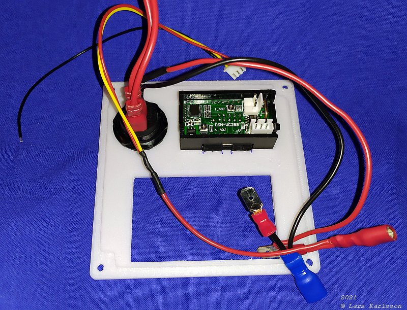
The switch has a small LED the lit up when in on position. Under the black insulation on the red cable is a small resistor soldered to limit the current to the LED, 1'200 ohm. 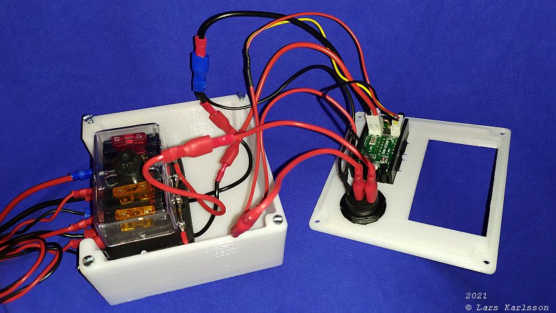
Lot of long cables, I couldn't nearly get on the lid. 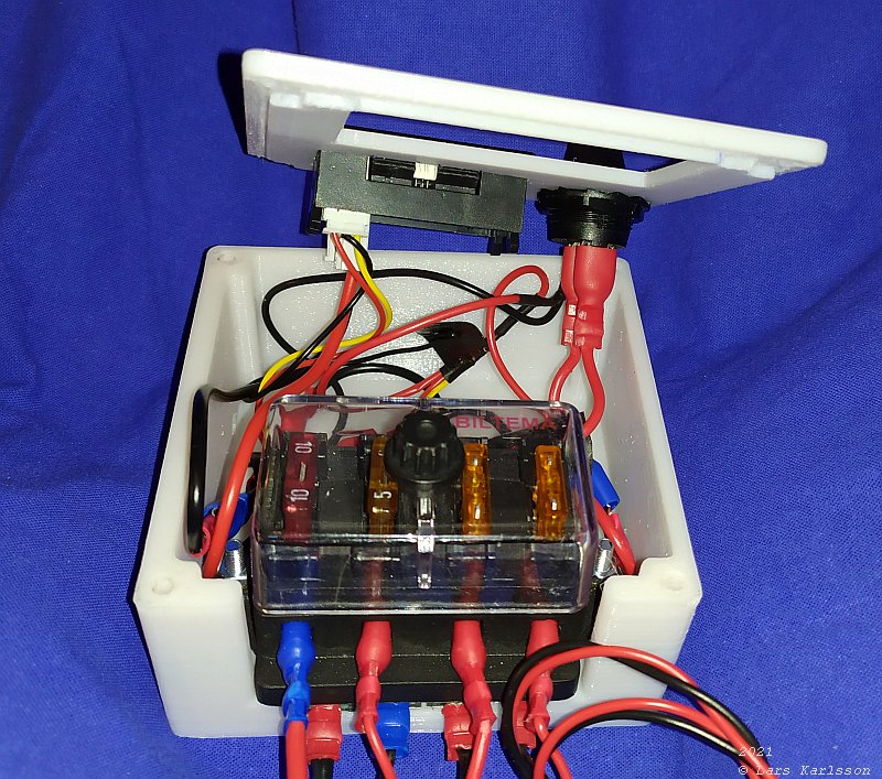
After I shortened the cables it was more space left and the lid slip in place (after some modifications). 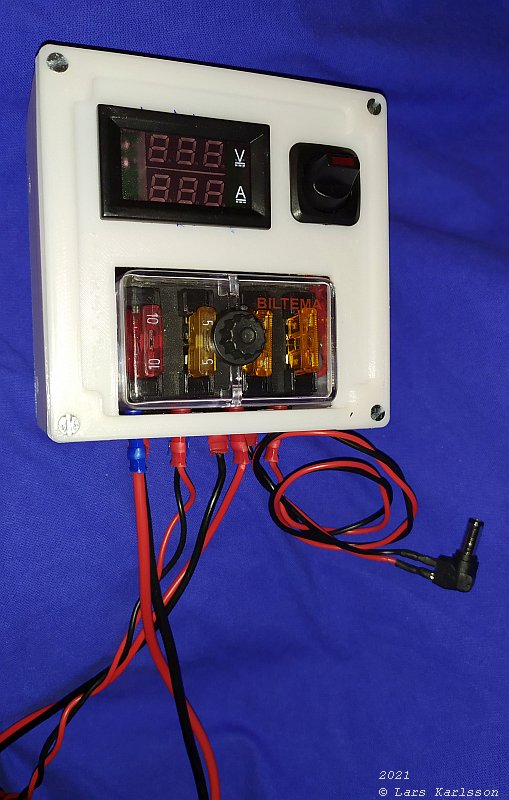
Nice look with the lid in place. 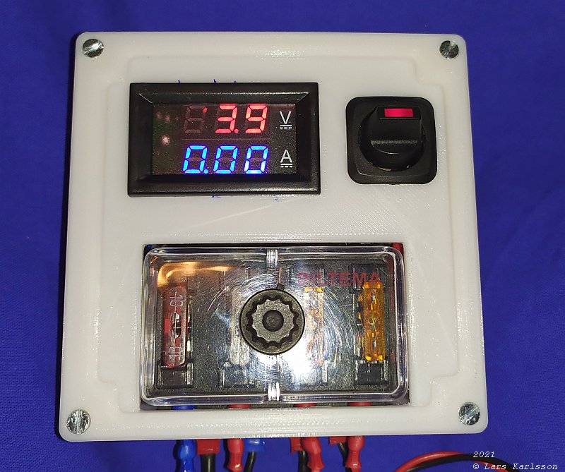
Power on. 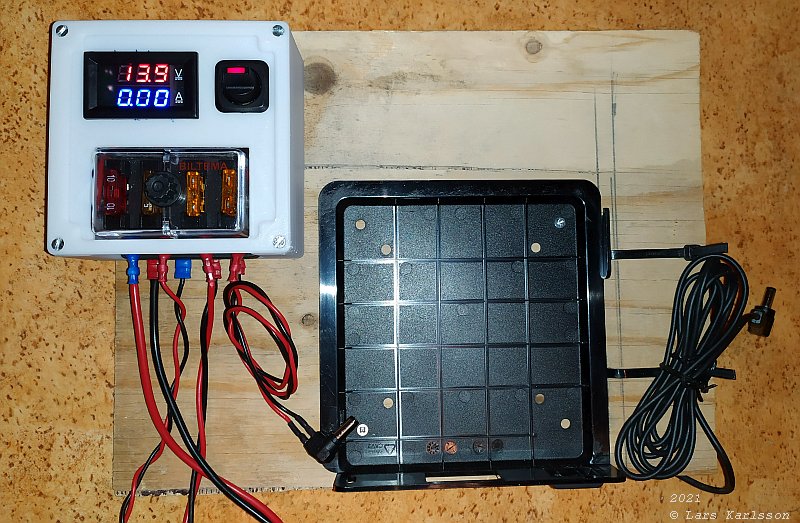
Big difference compare to the prototype board I had earlier. It will be a dream to use this power terminal. Only one thing left, a L shaped bracket that connect this box with the mini PC. Update: 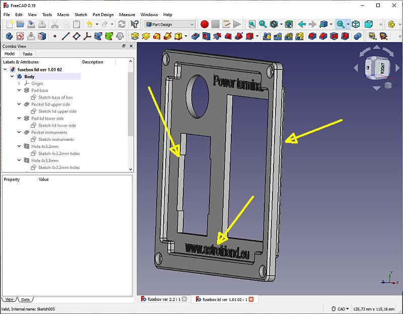
Adjusted the edges to the instrument, moved the fuse terminal edge towards the front, bigger text. |
|
|