|
Advertisement / Annons: |
3D CAD drawing:
|
Contents:
Note: |
1, CAD enclosure for my PC's peripherals:Introduction:I have had my mini PC mounted on a wooden board many years. Very practical when doing changes of the setup often, but give an ugly look. Now with new skills in CAD drawing and a working 3D printer it's time to do something about it. Mini PC prototype board: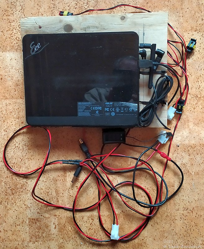
This is how my old prototype board looks, very practical but a shame to show my friends. The mini PC is an ASUS EEE box, used as an astroserver. It was on the way to be replaced it by a NUC PC, but then I realized that I could run my old mini PC direct on battery power. No reason anymore to replace it, I kept it. 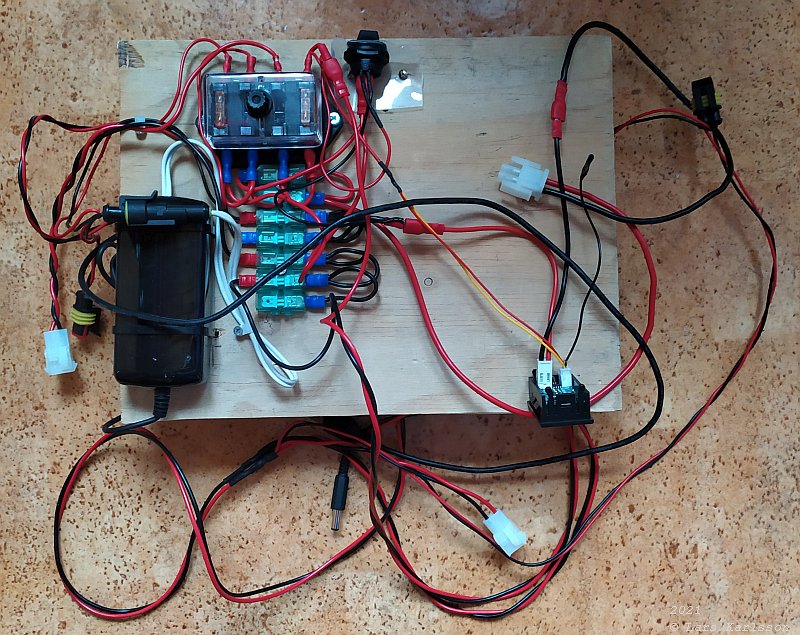
The backside of the wooden board, it have a fuse box, main switch, ampere & volt meter and a ground (-) terminal. The 12 Volt to 19 Volt converter I hope I don't have to use anymore. FreeCAD, 2D Sketch: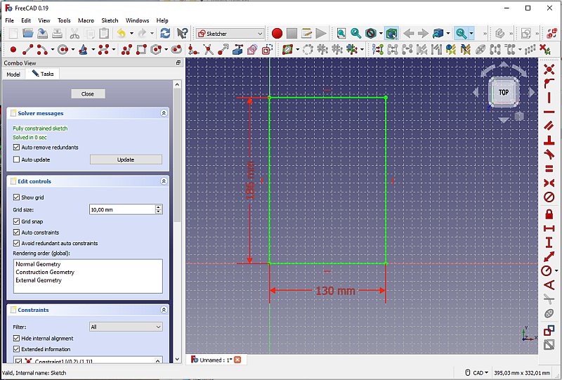
Start with a drawing from the ground, it will not be a complete enclosure, more a half cover of the PC and extra space where I can install the fuses, etc. After three hour, a 3D model: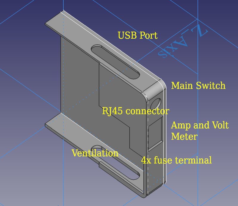
After some hours and a lot of changes I have come to this. It cover half the PC. Maximum diameter my printer can print is 230 mm and the height is about 300 mm. This was my first idea, later totally different. Minimizing the fuse box: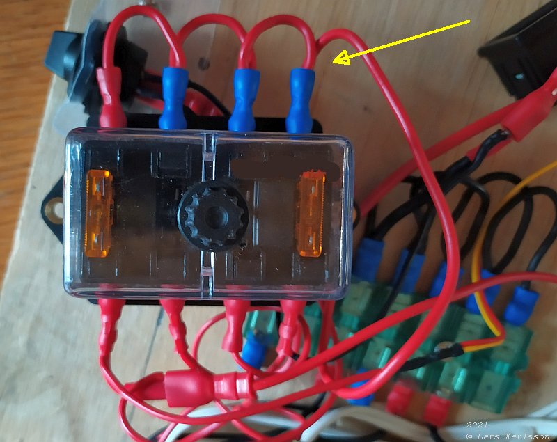
If I want to keep my fuse box I must make it more compact. Especially the cables to the common power on the backside. Same problem with the ground terminal in the background. These kind of fuses, knife fuses is easy to handle with frozen fingers. 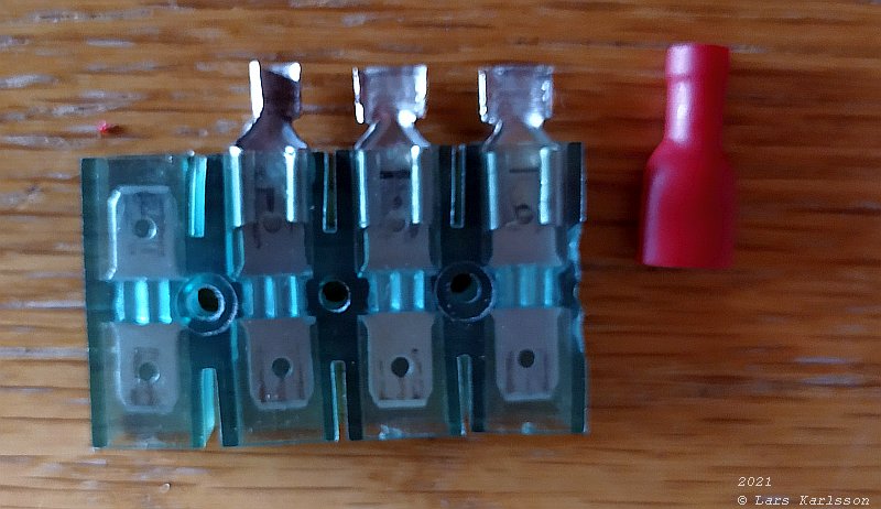
I took apart cable shoes and use them for soldering instead. 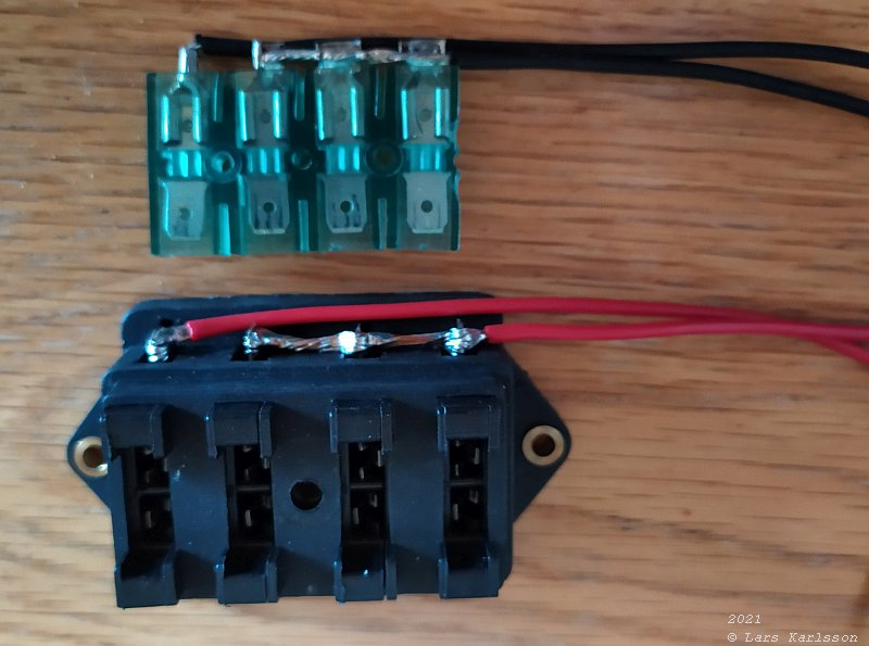
Much more compact now. Even better if I could find a fuse terminal with in coming power connected internally, also the ground terminal. I have found some for boats, but too big to fit here. The terminal to the left is the incoming power with its main fuse, 10 Amp. I also have to have a separate incoming minus wire, because the Ampere meter measure on the minus. Now I have enough of information to proceed with my CAD drawing. |
|
|